EURO STEEL BEAM LOAD AND RESTR AT AT BOTTOM FLANGE

Description
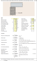
EURO STEEL BEAM LOAD AND RESTR AT AT BOTTOM FLANGE: Reference P360
This example illustrates the calculation of the design buckling resistance moment
for a beam with end restraint to the bottom flange only, and considers the effect of
destabilizing load. The beam is subject to a central point load and is supported at
either end on masonry walls spaced 7 m apart. Two cases are considered:
Case 1: the load is suspended from the bottom flange of the beam.
Calculation Reference
Structural Steel
Steel Eurocode Design
Design Buckling Resistance
Calculation Preview
Full download access to any calculation is available to users with a paid or awarded subscription (XLC Pro).
Subscriptions are free to contributors to the site, alternatively they can be purchased.
Click here for information on subscriptions.
Comments: 1
×
johndoyle-admin
9 years ago
Thanks again for another very useful calculation.


