Single Angle Bending with Torsion

Description
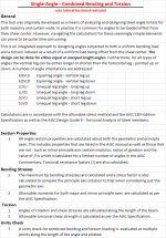
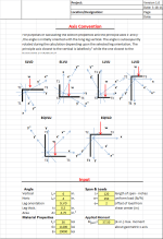
In practice it is common for angles to be loaded offset from their shear center. However, navigating the calculations for these seemingly simple elements can prove to be quite time consuming. This is an integrated approach to designing angles subjected to both a uniform bending load and a torsion induced as a result of a uniform load being offset from the shear center. The design can be done for either equal or unequal length angles. Furthermore, the vertical leg can be either longer or shorter than the horizontal leg - pointed up or down. Calculations are in accordance with the allowable stress method and the AISC 13th Edition Specification as well as the AISC Design Guide 9 - Torsional Analysis of Steel members. Section Properties
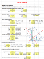
- All angle section properties are calculated about both the geometric and principle axes. This includes properties that are listed in the AISC manual as well as those that are not - such as minor principle axis section modulus, radius of gyration and the value of bw which is tabulated for a limited number of angles in the AISC Commentary. Torsional resistance factors (J) are also calculated. Bending Stresses
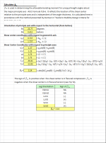
- The maximum tip bending stressses are calculated and a stress factor is also calculated to compare the principle axis solution to that when considering just the geometric axis
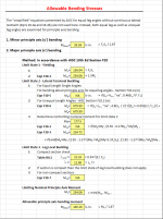
- Allowable moments for both major and minor principle axes are calculated as per the AISC Specification. Torsion
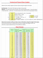
- Angles of rotation and shear stresses are calculated along the length of the beam
- Allowable torsional shear strength is calculated as per the AISC Specification. Unity Check
- A unity check for combined bending and torsion loading is evaluated at multiple points along the length of the angle and plotted. Deflections
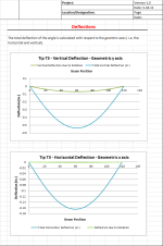
- Tip deflection of the angle is plotted for both the rotational component as well as the direct shear component of the applied loads.
- The vertical deflection ratio (to beam length) is calculated for reference. Users are left to determine their own acceptable design guidelines in terms of the allowable deflection. End Restraint Reactions
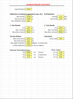
- Angles which are loaded about their geometric axes are subject to movement in two directions. Such movement requires an end restraint in both directions as well. The magnitude of the horizontal restraint is not insignificant and in certain circumstances can exceed the vertical reaction. The magnitude of the end restraints is calculated in both directions. User Note: These reactions ignore the stiffness of the elements attached to the angle. The analysis is limited to the following beam angles:
- Simply supported at ends and subjected to a uniform load
- Pinned ends for torsional loading and subject to a uniform torsion
- Beam is without continous lateral-torsional restraint along its length
- Shear stresses and normal stresses due to warping are ignored
- No axial loads
- Cb = 1.0
The worksheet is protected but without a password
Calculation Reference
Guide to Stability Design Criteria for Metal Structures
Structural Design
Steel Designers Manual
Calculation Preview
Full download access to any calculation is available to users with a paid or awarded subscription (XLC Pro).
Subscriptions are free to contributors to the site, alternatively they can be purchased.
Click here for information on subscriptions.
I did not plan on adding axial loads since this is not something I would typically deal with. This sheet was developed more for lintels and other similar constructions. I suspect that adding the axial component would involve a bit of work due to P-delta secondary effects.
As for the older version of Excel, I would recommend searching this forum and you will find a recommendation from John Doyle for an add on that will allow you to use this file from within older versions of Excel.
Thanks
Steve Capri

