Simple Hydrostatic Transmission system calculations
Description
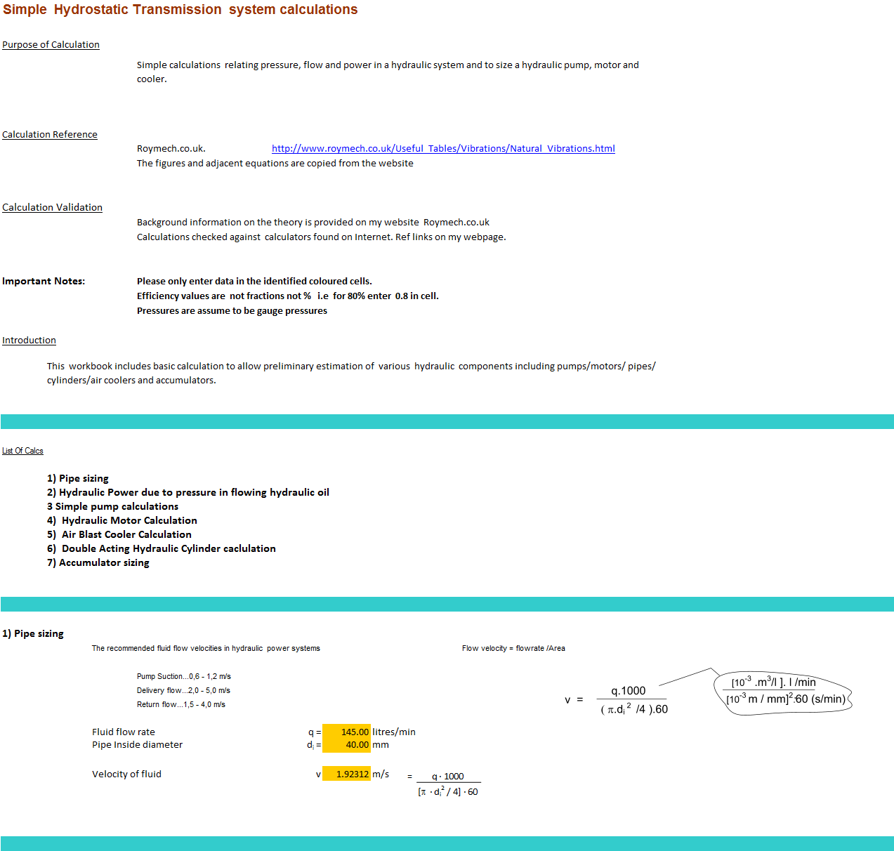
Simple calculations relating pressure, flow and power in a hydraulic system and to size a hydraulic pump, motor and cooler, accumulator and cylinder.
Further Information on the RoyMech website.
Calculation ReferenceHydraulics
Hydrauliv transmission
Hydraulic Circuit Design
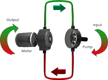
Hydraulic transmission is a widely used method for transmitting power in various industrial applications, such as construction equipment, factory automation, and aerospace. The hydraulic system consists of various components, including a pump, motor, cooler, accumulator, and cylinder, which work together to convert fluid power into mechanical power.
Pressure, flow, and power are key parameters in a hydraulic system, and they need to be carefully controlled to ensure efficient operation and prevent damage to the system components. The pressure in the system is typically controlled by a pressure relief valve, which releases excess pressure to prevent overloading of the components.
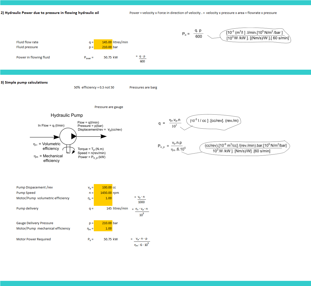
The flow rate in the system is determined by the hydraulic pump, which provides the required flow rate to the motor and other components. The size of the pump is determined based on the required flow rate and pressure, and it needs to be properly matched with the other components in the system to ensure efficient operation.
The power in the system is calculated using the following equation:
P = Q x ΔP
where P is the power, Q is the flow rate, and ΔP is the pressure drop across the system.
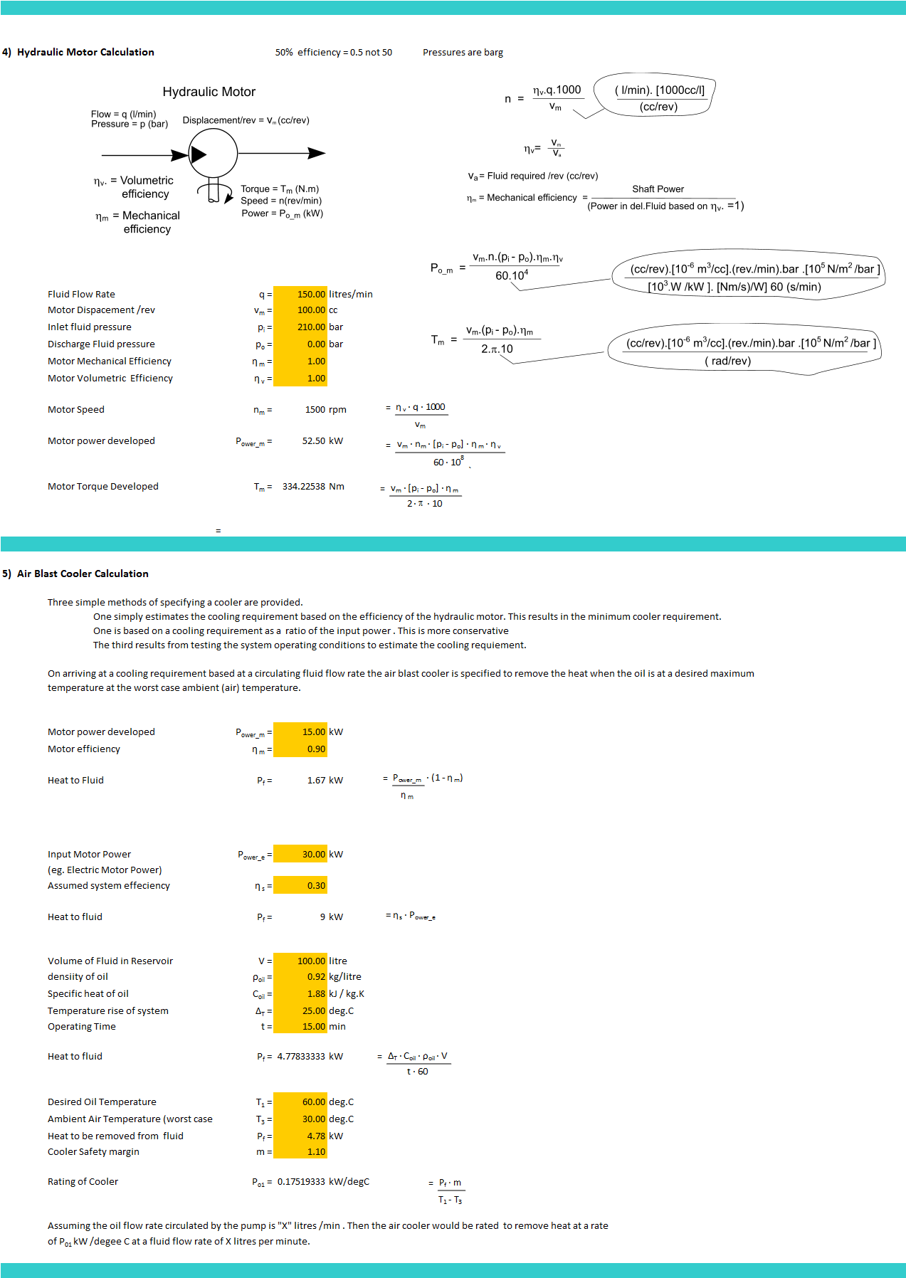
The hydraulic motor converts the fluid power into mechanical power, which is used to drive the load. The size of the motor is determined based on the required torque and speed, and it needs to be properly matched with the other components in the system to ensure efficient operation.
The hydraulic cooler is used to remove heat from the system, which is generated by the friction and other losses in the components. The size of the cooler is determined based on the amount of heat generated and the required cooling capacity.
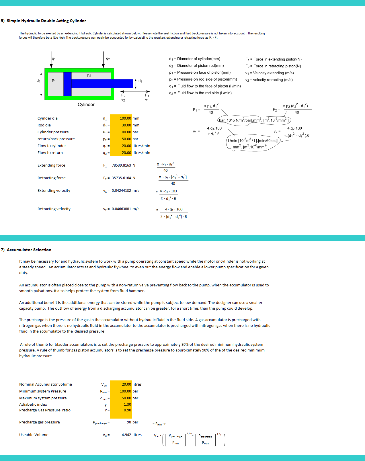
The hydraulic accumulator is used to store fluid under pressure, which can be released to provide additional power during peak demands. The size of the accumulator is determined based on the required pressure and volume, and it needs to be properly matched with the other components in the system to ensure efficient operation.
The hydraulic cylinder is used to convert the fluid power into linear motion, which is used to move the load. The size of the cylinder is determined based on the required force and stroke, and it needs to be properly matched with the other components in the system to ensure efficient operation.
Overall, sizing the hydraulic pump, motor, cooler, accumulator, and cylinder requires expertise in hydraulic engineering and fluid mechanics. The components need to be properly matched and designed to ensure efficient and safe operation of the hydraulic system.
Calculation Preview
Full download access to any calculation is available to users with a paid or awarded subscription (XLC Pro).
Subscriptions are free to contributors to the site, alternatively they can be purchased.
Click here for information on subscriptions.