Socket Pile Analysis And Design
Description
ANALYSIS AND DESIGN OF DRILLED SHAFT FOUNDATIONS SOCKETED INTO ROCK.
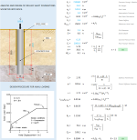
The following parameters can be set to evaulate this problem:
Concrete Young's Modulus, Soil Height, Axial Load, Atmospheric Pressure, Side Shear Resistance, Foctor Saffety, Maximum Axial Load, Pile Diameter, Socket Depth, Concrete Poisson Ratio, Rock Young's Modulus, Stiffness Parameters and Elastic Stiffness Equation.
Calculation Reference
Socket Pile Analysis And Design
ANALYSIS AND DESIGN OF DRILLED SHAFT FOUNDATIONS
Geotechnics
The analysis and design of drilled shaft foundations socketed into rock involve a series of steps to ensure adequate performance, structural integrity, and stability. Drilled shafts, also known as caissons or bored piles, are deep foundation elements that can transfer structural loads through weak soil layers to competent rock or stronger soil layers below. Socketing the shaft into the rock provides increased bearing capacity and resistance to lateral loads.
Here's an outline of the process for analyzing and designing drilled shaft foundations socketed into rock:
-
Gather necessary information: Collect site-specific information, such as rock properties, soil properties, groundwater conditions, structural loads, and applicable design standards.
-
Conduct a site investigation: Perform a geotechnical investigation to determine the depth to rock, the type and strength of the rock, and the properties of the overlying soil layers.
-
Define shaft geometry: Establish the diameter, length, and socket length of the drilled shaft based on the site requirements and constraints.
-
Determine the axial capacity: Calculate the axial capacity of the drilled shaft by considering the end-bearing capacity at the base of the socket (Qb) and the skin friction along the shaft and socket (Qs). The end-bearing capacity in rock can be calculated using the following formula:
Qb = Ap * q_rock
Where:
- Ap is the cross-sectional area of the drilled shaft
- q_rock is the allowable bearing pressure on the rock, which depends on the rock's compressive strength and the factor of safety
The skin friction in rock can be calculated using the following formula:
Qs = As * τ_rock
Where:
- As is the surface area of the shaft and socket in contact with the rock
- τ_rock is the allowable shear strength of the rock, which depends on the rock's shear strength and the factor of safety
-
Determine the lateral capacity: Analyze the lateral capacity of the drilled shaft using methods such as the p-y method or finite element analysis, considering the properties of the rock, the soil layers above the rock, and the stiffness and length of the shaft.
-
Design the shaft reinforcement: Design the reinforcement in the drilled shaft to resist the axial loads, bending moments, and shear forces induced by the structural loads and the lateral earth pressure. Use appropriate design methods, such as ACI 318 or Eurocode 2, to determine the required reinforcement and check the serviceability requirements (e.g., crack control and deflection).
-
Check for global stability: Analyze the global stability of the drilled shaft foundation system, considering the potential for deep-seated slope failures or other modes of instability.
-
Prepare design drawings and specifications: Develop detailed design drawings and specifications that include the shaft geometry, reinforcement layout, and construction requirements.
The analysis and design of drilled shaft foundations socketed into rock is a complex process that requires a thorough understanding of soil mechanics, rock mechanics, and structural engineering, as well as the application of appropriate design codes. It is always recommended to consult with experienced geotechnical and structural engineers to ensure a safe and efficient foundation design.
Calculation Preview
Full download access to any calculation is available to users with a paid or awarded subscription (XLC Pro).
Subscriptions are free to contributors to the site, alternatively they can be purchased.
Click here for information on subscriptions.


