Shafts
0 ContainersFiles in Shafts
Order by

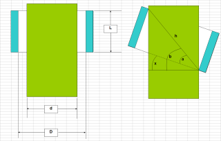

Keyed Shaft Design & Strength Analysis (ANSI B17.1)
Short Description:
This calculator's main function is to quickly and intuitively choose the proper machine key for a given shaft, and to obt...
Submitted By:
Last Modified
12 Sep 2023
Downloads:
34
Rating:


Shaft design.xls
Short Description:

Submitted By:
Last Modified
24 Jan 2007
Downloads:
420
Rating:

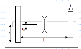
Shaft stress and deflection.xls
Short Description:
Submitted By:
Last Modified
24 Jan 2007
Downloads:
242
Rating:


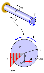
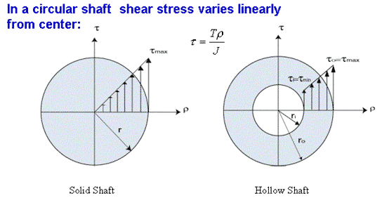
Shear stress and angle of twist of shaft under torsion.xls
Short Description:
Submitted By:
Last Modified
24 Jan 2007
Downloads:
345
Rating:

Shear stress in hollow shaft.xls
Short Description:
Submitted By:
Last Modified
24 Jan 2007
Downloads:
357
Rating:

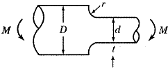
Stress Concentration Factor on Circular Shaft Under Bending.xls
Short Description:
Submitted By:
Last Modified
04 Mar 2011
Downloads:
105
Rating: