METHOD OF JET-GROUTING
Description
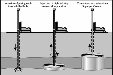
Drilling is typically performed using rotary drilling techniques and an external water flush with special drill rods and bits. Upon completion of the advancement of the drill rods to the design depth, the jet grouting process commences. The grout is injected through radial nozzles at high pressure and velocity, destroying the soil matrix and forming structural elements.
Many structures and geometries can be achieved by altering the parameters of the jetting procedure. The illustrated procedure details the creation of a jet grout column by continuous rotation of the drill string and controlled pre-set lifting increments.
Calculation Reference
Jet Grouting
Jet grouting is a ground improvement technique used to create in-situ soil-cement columns, panels, or walls by injecting high-pressure fluids (usually a slurry of water, cement, and sometimes bentonite or other additives) into the ground. The high-pressure fluid breaks up the soil structure and mixes it with the cement slurry, creating a soil-cement material that solidifies and forms the desired ground improvement element.
Jet grouting has several applications in geotechnical engineering, including:
- Improving the soil's strength and stiffness to support foundations, slopes, embankments, and other structures.
- Creating underground cut-off walls to control groundwater flow or contain contaminants.
- Providing temporary or permanent excavation support, such as constructing retaining walls or diaphragm walls for deep excavations or tunneling projects.
- Reducing soil permeability to minimize seepage and control groundwater levels.
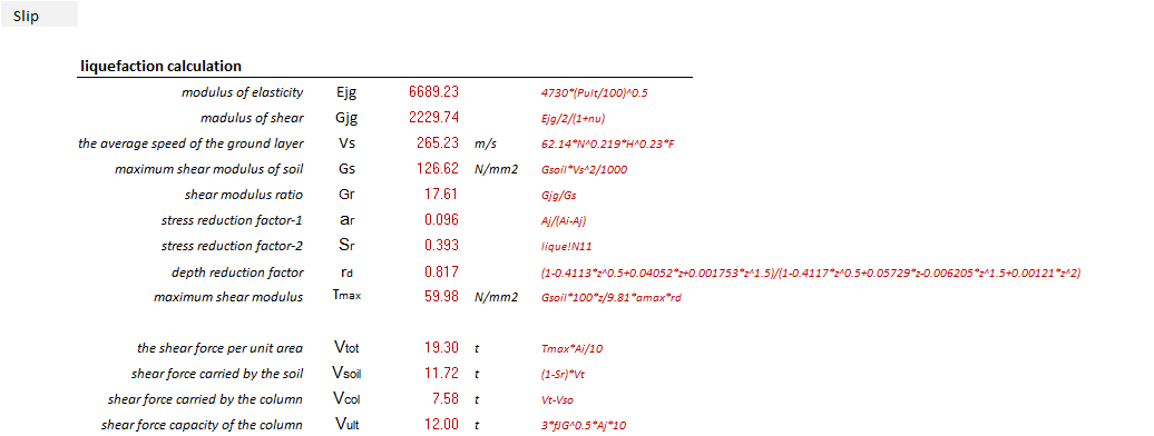
- Stabilizing soils prone to liquefaction during earthquakes.
There are three main types of jet grouting techniques:
-
Single fluid jet grouting: This method uses a single high-pressure fluid (cement slurry) to break up the soil and create the soil-cement mixture. It is suitable for granular soils with low fines content.
-
Double fluid jet grouting: This method uses two fluids: a high-pressure fluid (usually water) to break up the soil, and a second fluid (cement slurry) that mixes with the broken-up soil to create the soil-cement mixture. It is suitable for a wider range of soil types, including granular and cohesive soils.
-
Triple fluid jet grouting: This method uses three fluids: a high-pressure fluid (usually water) to break up the soil, air to help control the jet and improve the efficiency of the process, and a cement slurry to mix with the broken-up soil to create the soil-cement mixture. This method is suitable for a wide range of soil types and provides better control over the grout penetration and mixing process.
Jet grouting requires specialized equipment and skilled operators to perform effectively. The design and execution of jet grouting projects should be done in collaboration with experienced geotechnical engineers and contractors, taking into account the specific soil conditions, structural requirements, and project constraints.
To calculate the bearing capacity of a jet-grouted element, follow these steps:
-
Determine the improved soil properties: After jet grouting, the soil-cement element will have different properties than the original soil. Conduct laboratory tests on samples of the jet-grouted material to determine its compressive strength, unit weight, and other relevant parameters.
-
Determine the geometry of the jet-grouted element: Obtain the dimensions of the jet-grouted element, such as its diameter (for a column) or thickness (for a panel or wall). This information should be available from the design or as-built drawings of the ground improvement project.
-
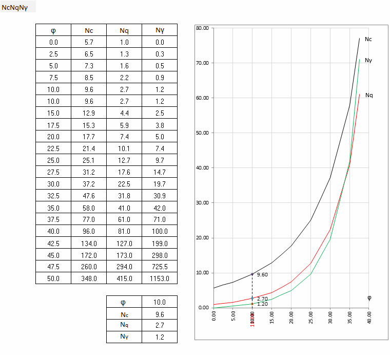
Calculate the ultimate bearing capacity: The ultimate bearing capacity (qu) of the jet-grouted element can be calculated using bearing capacity theories, such as the Terzaghi's bearing capacity equation or the Meyerhof's bearing capacity equation. These equations consider the improved soil's cohesion (c'), friction angle (φ'), unit weight (γ'), and the geometry of the element, as well as any surcharge loads or water table effects.
For example, using Terzaghi's bearing capacity equation for a strip footing on a cohesive soil, the ultimate bearing capacity is:
qu = c' * Nc + q * Nq + 0.5 * γ' * B * Nγ
Where:
- c' is the cohesion of the improved soil
- Nc, Nq, and Nγ are bearing capacity factors that depend on the friction angle (φ') of the improved soil
- q is the surcharge load acting on the element
- γ' is the unit weight of the improved soil
- B is the width of the footing
- Calculate the allowable bearing capacity: Divide the ultimate bearing capacity by a factor of safety to obtain the allowable bearing capacity (qa):
qa = qu / FS
Where:
- FS is the factor of safety, typically ranging from 2 to 4 depending on the project's requirements and level of uncertainty.
Keep in mind that this process provides a simplified approach to calculate the bearing capacity of jet-grouted elements. In practice, more advanced methods, such as numerical modeling or in-situ testing, may be required for complex situations or where more accurate predictions are needed. It is always recommended to consult with experienced geotechnical engineers when determining the bearing capacity of jet-grouted elements.
Calculation Preview
Full download access to any calculation is available to users with a paid or awarded subscription (XLC Pro).
Subscriptions are free to contributors to the site, alternatively they can be purchased.
Click here for information on subscriptions.
