ThermalStratificationStress.xls
Description
This spreadsheet calculates the temperatures, displacements and stresses in an unrestrained cylindrical wall where there is heat transfer to an internal fluid that is stratified by hot and cold layers over a specified depth. The case of a step change in fluid temperature is also considered.
Stress of Vertical Cylindrical Vessel for Thermal Stratification of Contained Fluid
This spreadsheet calculates the temperatures, displacements and stresses in an unrestrained cylindrical shell where there is heat transfer to an internal fluid that is stratified by hot and cold layers. The outer surface of the shell is assumed to be insulated.
The method used is derived from a technical paper published by Ichiro Furuhashi. The reference and link is provided in the 'Input' worksheet.
The introduction to the published work is copied here:
Introduction
Various thermal loads are induced in elevated temperature systems, such as nuclear power plants. The load caused by the thermal stratification of contained fluid is one of those loads (Moriya et al., 1987; Bieniussa & Reck, 1996; Kimura et al., 2010). The thermal stratification is phenomenon under the condition of insufficient forced-convection mixture, where a denser fluid layer of lower temperature locates beneath a lighter fluid layer of higher temperature (Haifeng et al., 2009).
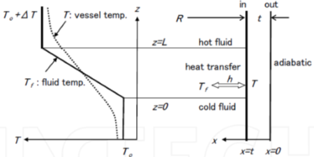
A conventional design evaluation method of vessel stress assumes an axial vessel temperature profile consisting of a straight line with the maximum fluid temperature
gradient as shown in the top of Fig.1, and applies cylindrical shell theory for stress solution (Timoshenko & Woinowsky, 1959). The conventional method gives conservative solutions of thermal stresses that are proportional to the temperature gradient, and hence leads to narrower design windows.
In actual conditions, thermal stress is smaller than that from the conventional method, because of relatively moderated temperature profile due to attenuation by heat transfer on the inner surfaces and by heat conduction in vessel walls as shown in the bottom of Fig.1, as well as the cancellation of stresses at both ends of the thermal stratification section that have opposite signs generated by the reverse temperature changes. The consideration of such effects conventionally requires FEM heat conduction analyses taking the heat transfer with fluid into account and the subsequent FEM thermal stress analyses based on the above results. However, the FEM analyses are not suitable for a design work which places a high priority to get design perspective with rapid estimation.
Discussion
As stated in the paper the method used is designed to give a more realistic assessment of stresses when considering conductivity within the shell. Calculated stresses are accurate for relatively low Biot numbers, but are less so for higher Biot numbers when temperatures in the shell would approach a theoretical discontinuous distribution. This is more evident in the case of step change in temperature when the method underestimates the hoop stress at this gross discontinuity.
Maximum axial bending stresses occur away from the discontinuity, however, and are less affected. To supplement the method used in the spreadsheet, these limiting stresses are calculated for the theoretical cases of discontinuous temperatures in the shell.
Input
Values for the cylindrical shell geometry together with the material properties are required
The fluid temperature is defined by the temperature below the stratification layer and the increase in temperature through that layer distance, L. Forced convection to the fluid is defined by a inputting a heat transfer coefficient.
The length of shell, S, is also required, however this value is purely used to provide a distance for plotting the results against that distance. For calculation purposes the shell is assumed to be infinitely long and remote from any restraints that may apply to the cylindrical wall that may affect stresses.
The user can select units based upon mm or ft for comvenience only. Appropriate consistent units are shown for other required properties. No conversion of units is carried out in the spreadsheet.
Output
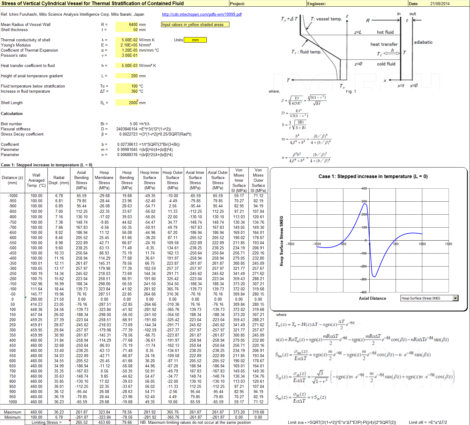
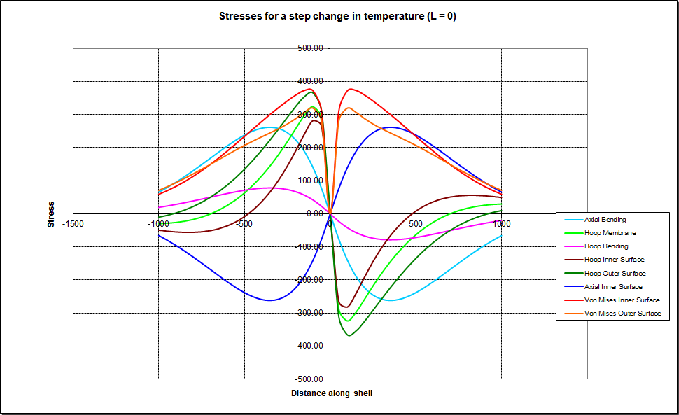
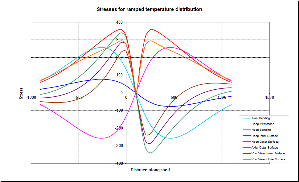
Two cases are considered in the analysis; that of a step change in fluid temperature, and secondly a ramped change in temperature over the stratified layer of height L.
In both cases shell temperatures, displacements and stress components are calculated toegether with the Von Mises Stress Intensity at both inner and outer surfaces of the shell.
In the case of a step change in temperature, the limiting stress for a theoretical step change in shell temperature, ie. an infinite heat transfer coefficient, is also calculated for axial bending and hoop membrane and bending stress. Note that the limiting stress for each component occur at different positions along the
shell and thus can not be combined to derive the Von Mises stress intensity at one position.
Results are tabulated and plotted in the accompanying graphs where the user can select the particular component to plot via the drop down box.
For completeness, all stress components are plotted together in a single graph in the worksheets 'Chart-StepChange' and 'Chart-Ramp'.
Note that for assessment purposes against pressure vessel standards the calculated stresses from thermal loads are classed as secondary. Combined with primary stresses from mechanical loads the allowable stress intensity is generally limited to twice the yield strength of the shell. Reference should be made to the appropriate pressure vessel design code for guidance.
Calculation Reference
Thermal Stratification Stress
Thernal Stress Analysis
Heated Cylindrical Vessel
Calculation Preview
Full download access to any calculation is available to users with a paid or awarded subscription (XLC Pro).
Subscriptions are free to contributors to the site, alternatively they can be purchased.
Click here for information on subscriptions.