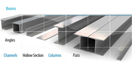
Beams
0 ContainersFiles in Beams
Order by


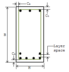
ACI318-08 RC Beam
Short Description:
Submitted By:
Last Modified
24 Nov 2011
Downloads:
350
Rating:


ANALYSIS & DESIGN OF RC BEAM AS PER ACI 318-08
Short Description:
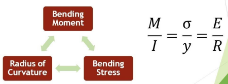
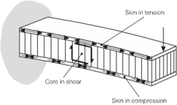
The Basic Concept: When a concrete beam bends under load, the concrete on one side gets compressed while the other side gets stretched (tension). S...
Submitted By:
Last Modified
06 Aug 2020
Downloads:
4
Rating:

Beam Design Functions.zip
Short Description:
Submitted By:
Last Modified
19 Aug 2008
Downloads:
371
Rating:

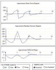
Beam Moment and Shear
Short Description:

Submitted By:
Last Modified
30 Jan 2015
Downloads:
414
Rating:

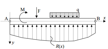
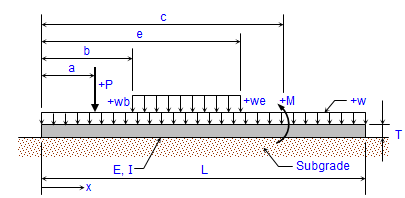
Beam on elastic foundation
Short Description:
Submitted By:
Last Modified
01 Aug 2015
Downloads:
193
Rating:

Beam with stress.xls
Short Description:
Submitted By:
Last Modified
13 Feb 2009
Downloads:
761
Rating:

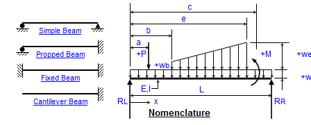
BEAMANAL (metric).xls
Short Description:

Submitted By:
Last Modified
09 Oct 2009
Downloads:
724
Rating:


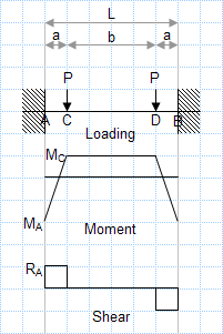
Built-in beam with 2 symmetric point loads.xls
Short Description:
Submitted By:
Last Modified
09 Dec 2007
Downloads:
456
Rating:


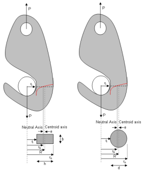
Curved Beam Design
Short Description:
Submitted By:
Last Modified
17 Jun 2015
Downloads:
202
Rating:


Design of Rectangular Column
Short Description:
Submitted By:
Last Modified
05 Apr 2013
Downloads:
190
Rating:

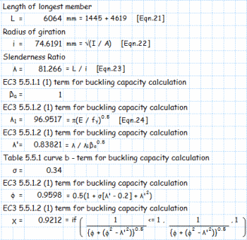
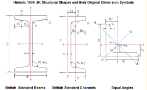
EC3 Calculations.xls
Short Description:
Submitted By:
Last Modified
09 Dec 2007
Downloads:
545
Rating:


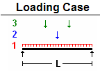
Equialent UDL from Point Loads in Beam
Short Description:
Calculating the equivalent distributed load from a set of point loads in a beam can be highly beneficial to an engineer for several reasons...
Submitted By:
Last Modified
13 Mar 2024
Downloads:
19
Rating:


Grating Aluminum Beam Design
Short Description:
Submitted By:
Last Modified
04 Sep 2012
Downloads:
235
Rating:


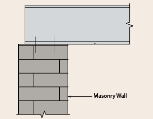
Light-weight Composite Beam Design
Short Description:
Submitted By:
Last Modified
30 May 2012
Downloads:
206
Rating:

Loading Calculation Sheet.xlsx
Short Description:
Beam bending theory is a fundamental concept in structural engineering and solid mechanics that deals with the deformation and stress distr...
Submitted By:
Last Modified
02 Jan 2023
Downloads:
19
Rating:

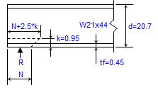
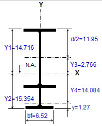
LRFD Bending Member Design
Short Description:
Submitted By:
Last Modified
22 Jun 2016
Downloads:
215
Rating:

LRFD Tension Member Design
Short Description:

Submitted By:
Last Modified
23 Jun 2016
Downloads:
122
Rating:


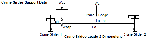
Monorail runway beam design as per Eurocode
Short Description:
Submitted By:
Last Modified
18 Jul 2018
Downloads:
136
Rating: