FRAME.xls

Description
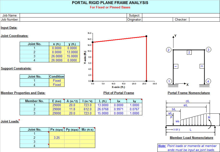
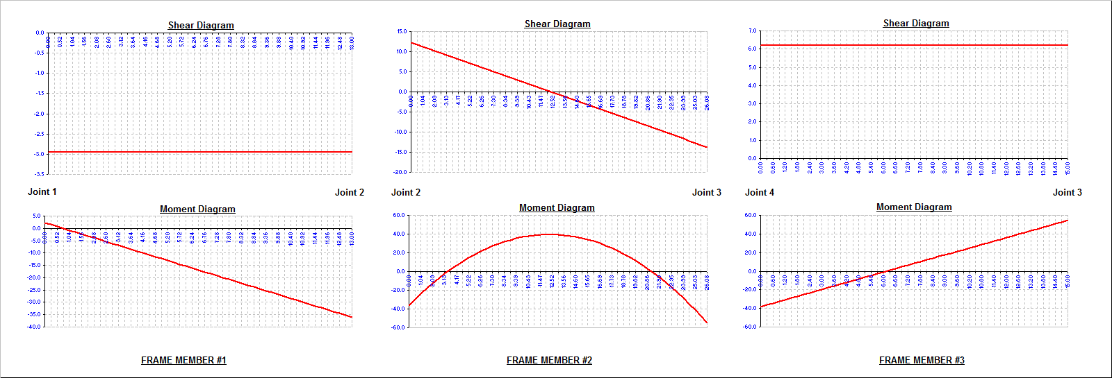
"FRAME" is a spreadsheet program written in MS-Excel for the purpose of plane frame analysis of portal and gable rigid plane frames subjected to various types of loading. Specifically, the "stiffness matrix" method of analysis is used to determine the unknown joint displacements, support reactions, and member end forces. Individual frame members are also analyzed to determine the shears and intermediate moments. Plots of both the shear and moment diagrams are also produced. Also, the frame is drawn for visual confimation of geometry/configuration.
This program is a workbook consisting of three (3) worksheets, described as follows:
- Doc - Documentation sheet
- Portal Frame - Portal rigid plane frame analysis
- Gable Frame - Gable rigid plane frame analysis
Program Assumptions and Limitations:
1. This program uses the "stiffness matrix" method of analysis and four (4) following basic analysis assumptions:
a. Members must be of constant cross section (E and I are constant for entire length).
b. Deflections must not significantly alter the geometry of the problem.
c. Stress must remain within the "elastic" region.
d. Since this is a "first-order", linear analysis, the effects of "P-delta" and shear deformation are not included.
(However, significant effects due to shear deformation are limited to very short and deep members.)
2. Additional assumptions and features are as follows:
a. Frame support joints may each be either fixed or pinned.
b. Frame support joints may be at different levels (elevations).
c. Columns must be vertical (cannot be sloped).
d. For a portal frame, the top (roof) member may be flat or sloped in either direction.
3. A vertical load, horizontal load, and externally moment may be applied to any of the joints of the frame. These joint loads are to be applied in "global" axes directions. Note: Joint loads applied directly at supports are merely added directly to support reactions and are not reflected in member end force values.
4. On any individual member, this program will handle up to five (5) full uniform, partial uniform, triangular, or trapezoidal loads, up to ten (10) point loads, and up to four (4) externally applied moments. For vertical members, distributed loads and point loads are input in a "X-Global" sence of direction. For flat or sloped top (roof) members, distributed loads may be applied global over actual member length or applied global over the "projected" member length. Program designations are "Y-Global", "Y-Projected", "X-Global", and "X-Projected". For a flat top (roof) member of a portal frame, "Y-Global" and "Y-Projected" loads produce the same results. Uniformly distributed gravity (dead or live) load would be an example of a "Y-Global" distributed load on a sloped top (roof) member, while lateral uniformly distributed wind load on sloped top (roof) member would be an example of an "X-Projected" distributed load. A uniformly distributed load such as wind suction perpendicular (normal) to a sloped top (roof) member must be resolved into Y-Global and X-Global component values by user.
5. This program will calculate the member end reactions, the member end forces (axial, shear, and moment), the member maximum positive and negative moments (if applicable), and the joint displacements. The calculated values for the maximum moments are determined from dividing the member into fifty (50) equal segments with fifty-one (51) points, and including all of the point load and applied moment locations as well. (Note: the actual point of maximum moment occurs where the shear = 0, or passes through zero.)
6. The user is also given the ability to select an AISC W, S, C, MC, or HSS (rectangular tube) shape to aide in obtaining the required moment of inertia for input. (This facility is located off to the right of the main page.)
7. This program contains numerous “comment boxes” which contain a wide variety of information including explanations of input or output items, equations used, data tables, etc. (Note: presence of a “comment box” is denoted by a “red triangle” in the upper right-hand corner of a cell. Merely move the mouse pointer to the desired cell to view the contents of that particular "comment box".)
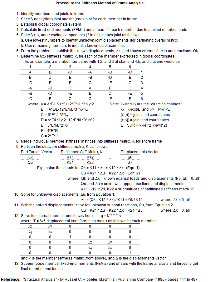
Procedure for Stiffness Method of Frame Analysis:
1.Identifiy members and joints in frame
2.Specify near (start) joint and far (end) joint for each member in frame
3.Establish global coordinate system
4.Calculate fixed-end moments (FEM's) and shears for each member due to applied member loads
5.Specify x, y, and z coding components (3 in all) at each joint as follows:
a. Use lowest numbers to identify unknown joint displacements (for partioning overall matrix)
b. Use remaining numbers to indentify known displacements
6.From the problem, establish the known displacements, Dk, and known external forces and reactions, Qk
7.Determine 6x6 stiffness matrix, k', for each of the member expressed in global coordinates
8.Merge individual member stiffness matrices into stiffness matrix, K, for entire frame
9.Partition the structure stiffness matrix, K.
10.Solve for unknown displacements.
11.With the solved displacements, solve for unknown support reactions.
12.Solve for internal member end forces
13.Superimpose member fixed-end moments (FEM's) and shears with the frame analysis end forces to get final member end forces
Reference: "Structural Analysis" - by Russel C. Hibbeler, Macmillan Publishing Company (1985), pages 441 to 497
Calculation Reference
Structural Analysis - Hibbeler
Modern Formulas for Statics and Dynamics
Structural Steel Designer's Handbook
Calculation Preview

Uploaded
11 Oct 2016
Submitted By:
Last Modified
11 Oct 2016
File Size:
3,765.50 Kb
Downloads:
1478
File Version:
1.2
Full download access to any calculation is available to users with a paid or awarded subscription (XLC Pro).
Subscriptions are free to contributors to the site, alternatively they can be purchased.
Click here for information on subscriptions.
Do you have an excel sheet for plane framework square or rectangular framework supported on 4 corner columns like shown in the link above?
Thanks
Rahul
I have made the corrections to the comment boxes.
Thanks for this interresting tool.
I would like to have more information regarding the limitations applied to members 1 and 3 that have to be vertical according "Portal Frame" sheet "joint coordinates" table.
From what I have seen, stiffness matrices seems correctly rotated whatever the member and I have checked versus a small beam FEM and results are identical for the configuration attached or others always loaded on member 2.
Thanks a lot for your answers.
Best regards.
Nicolas
Also, since a few people had asked me about it, I added some information at the bottom of the "DOC" worksheet describing how the user can manually implement an iterative solution to account for P-Delta ("Big" Delta) effects (2nd order) on the columns of a frame.
This workbook is now version 1.1.