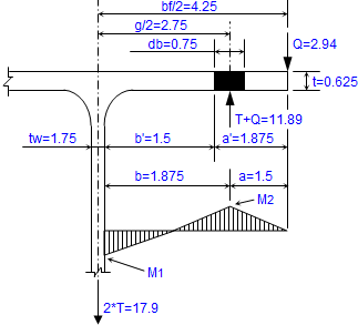
The ExcelCalcs website is developed is wholly owned by MoreVision Limited. Their analysis, testing and calculation services have been used for railway vehicles, construction equipment, oil and gas plant, cranes and mechanical items for theme parks since 1995. Click the links below to see some case studies:
- Finite Element Analysis Services: Stress Analysis, Fatigue Analysis, Vibration Analysis, Seismic Analysis, Thermal Analysis, Impact/Crash Analysis & Optimisation.
- Structural Testing Services: Strain gauge tests, Accelerometers, Signal Processing & Analysis of Test Results.
- Calculation Services: Structural Design & Sizing, Bolted Joint Assessment, Welded Joint Assessment, Approval to Industry Codes & Standards, Structural Design Troubleshooting, Failure Investigations, Performance Estimation, System Optimisation, Mechanical Simulation, Mechanism Design, Machine Element Design, Vibration & Damping Control, Mathematical Modelling & Loading Calculations.
- Training: MoreVision offers a number of training courses.
Our client list includes Shell, Bombardier, Siemens, Volvo and Disney:

|
|
|
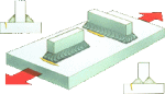
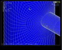
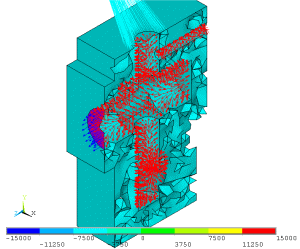
Typically model includes boundary temperatures, heat input/output, the
relevant conduction properties, convection surface details and
radiation surface details.
|
|
|
ANSYS Script Generators |
|
|
Thermal Analysis |
|
|
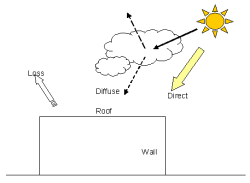
 When a component
is subject to extreme temperatures or a high thermal flux its is often
necessary to perform a thermal analysis to determine the temperature
distribution throughout the component. This will check
that operational temperature limits of constituent parts are not
exceeded or to determine the need for safety guards to protect
personnel from extreme heat (or cold).
When a component
is subject to extreme temperatures or a high thermal flux its is often
necessary to perform a thermal analysis to determine the temperature
distribution throughout the component. This will check
that operational temperature limits of constituent parts are not
exceeded or to determine the need for safety guards to protect
personnel from extreme heat (or cold). 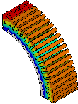 Three
variants of a water cooled electrical motor stator were
modelled, each variant had a slightly different method of cooling. Heat inputs and
convection surfaces were applied to the model and the steady
state temperature distribution was determined.
This gave the information the designers required to choose the most
efficient cooling system.
Three
variants of a water cooled electrical motor stator were
modelled, each variant had a slightly different method of cooling. Heat inputs and
convection surfaces were applied to the model and the steady
state temperature distribution was determined.
This gave the information the designers required to choose the most
efficient cooling system.
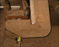
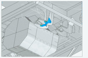
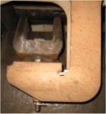
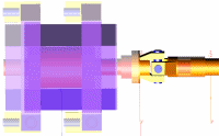
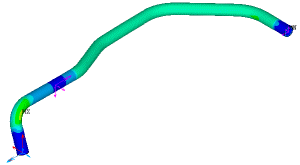
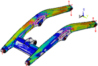
The structural failure of a traction motor mounting bracket occurred in service. Fortunately the motor was prevented from falling onto the tracks by a cardan shaft protection ring thus preventing a catastrophe but the issue was taken very seriously by our client and was quickly elevated to the executive level. The animation shows how the vehicle mounted traction motor drives a cardan shaft which drives the wheels via a bogie mounted gearbox. MoreVision was brought in by the executive engineering managers to devise and implement a technical strategy that would guarantee that no further bracket failures would occur in service. This project covered a period of some 18 months working very closely
with the vehicle manufacturer, the service providers, depot staff and
test sub-contactors.
Our brief was simply:
• to determine risk mitigation actions to keep the fleet working in service.
• to develop a long term 'safe-life' solution.
Initial Analysis
Within hours we began to gain an understanding of the problem using a simple finite element model. This showed that the bracket was particularly susceptible to lateral loading. We gained enough understanding of the bracket fatigue prone areas to position number of strain gauges for an investigative on track test.
Initial On-track Testing
The test train was taken onto the track in a number of configurations (cardan shaft attached, removed and freewheeling). This would help us determine the relative magnitudes of possible fatigue mechanisms. A spotlight was quickly thrown on the importance of low magnitude but high frequency stresses arising from cardan shaft's out of balance forces. This problem could only get worse with time as the cardan shaft wears.
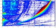
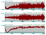
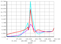
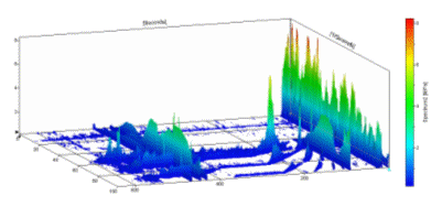
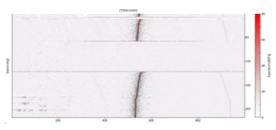
The problem was exacerbated by the dynamic response of the motor rubber mounts whose resonant frequencies coincided with typical line running speeds. The waterfall plot above shows the strain results in the frequency domain (response is plotted against frequency [x] and speed [y]). It shows the maximum response at the same frequency as the cardan shaft rotational frequency. The set of three overlayed curves above shows strain verses time as the train accelerates from 0 to 200kmph. The top graph shows the raw signal (unfiltered); the middle graph shows the high frequency content of the signal (mainly associated with rotation of the cardan shaft); the bottom graph shows the low frequency content of the raw signal (mainly associated with motor torque effects). Both high frequency and low frequency signals had an influence on fatigue life of the bracket. On-track testing helped us to:
- understand the most important fatigue driving mechanisms.
- understand the importance of cardan shaft loading and the dynamic response of the motor on its resilient rubber mounts.
- determine stress signals for input to crack growth models. This forms the basis of an inspection regime to guarantee passenger safety.
- redefine new loadcases to develop a long term solution.
Until a long term solution could be devised and implemented it was necessary to undertake risk mitigation actions to ensure the the fleet was running without any risk to passengers safety. This was possible by establishing a crack inspection regime. Ultra-sound Inspection trials were set up to determine the minimum detectable crack size. Simultaneously, using samples of stress measured during the on-track testing and incorporating stress factor to account for cardan shaft ageing, it was possible to calculate an inspection interval to guarantee detection of a crack before a bracket failure.
Further Risk Mitigating Actions
The safety of the fleet was increased further by introducing a polished weld toe detail. This improved the situation in the following ways:
- it removes weld toe material (this is inherently poor quality material with many defects and flaws that make it susceptible to fatigue failures).
- it repositions the maximum stress away from poor quality weld material and into good quality polished parent material. Thus the initiation of crack growth was less likely.
- it increases inspectability of the bracket (smaller cracks could be reliably detected thus cracks can be repaired sooner and the safety of the fleet is increased).
It was difficult explaining that removal of material from a critical section would result in a fatigue strength improvement but the method was endorsed by supporting finite element analysis and expert papers. The detail was easily and quickly introduced by a drilling and polishing operation.
Moitoring the Fatigue Regime
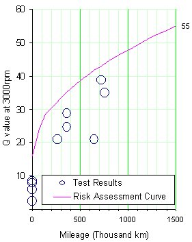
Joints in the cardan shaft wear with time and increase the amount of out of balance force acting on the traction motor mounting brackets. Our analysis and calculations showed that we needed to decrease the inspection interval to accounted for an ever increasingly aggressive fatigue environment. It was important to monitor the cardan shaft loading by continuous testing of cardan shafts on a balancing machine. The problem was exacerbated when a new risk due to heat damaged rubber motor mounts was identified. Additional stress factors were introduced to account for the new risk and the inspection period was reduced accordingly. Over the monitoring period the inspection regime managed to find a number of cracks which were safely repaired before they became anywhere close to the critical size for fracture of the bracket.
Dynamic Analysis
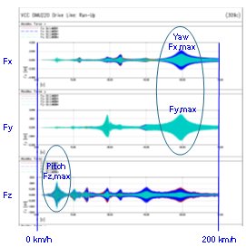
A non-linear dynamic model was developed by a partner in Switzerland to study the dynamic behaviour of the traction motor on its resilient mounts excited by the cardan shaft out of balance forces from 0 to 200kmph. Low speed pitching mode gives peak vertical loading on the motor mounting brackets. High speed yaw mode gives peak longitudinal and lateral loading. All modes of vibration are evident in the plot of bracket forces verses speed. It is notoriously difficult to interpret the results of dynamic analysis and define loadcases for a finite element stress model. The initial approach was to take the maximum loads in each direction and apply them in the most adverse combination. This proved to be too conservative and an alternative approach was developed. It was possible to determine stress time histories at fatigue critical locations using dynamic model output. Damage could then be calculated using rain flow counting methods. Once the approach was developed, design iteration which included the rubber mount manufacturer allowed us to optimise the stiffness and damping characteristics of a new high temperature motor mount. This was to become an important part of the solution.
Long Term Solution

A long term solution is developed comprising:
- New 'riveted in' reinforced front brackets.
- Structural enhancements including TIG dressing of weld toes and profiling plates to introduce softener details at weld ends.
- Inclusion of a dynamically optimised high temperature motor mount.
- Cardan shafts monitoring and control system.
The solution was developed using predictive analysis techniques and validated by monitoring critical strain gauge locations over some 20,000km. In addition the predicted benefit of a new high temperature rubber motor mount was also supported by on track testing. The final solution has an unmonitored safe life of 30 years.
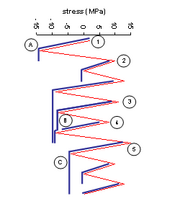
What is fatigue?
|
|
|
|
|
|
|
|
DESCRIPTION OF THE FAILURE
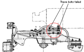
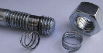
As always our approach is to propose solution found through understanding the mechanics of failure. A railway vehicle antennae raft is cantilevered the bogie transom by 4 M16 bolts. The bolts had repeatedly failed in service and was considered a severe hazard as a detached raft could in a worst case scenario derail a train and result in loss of life. MoreVision were invited to investigate the failure. The bolt samples were sent to a metallurgical laboratory and examination of the bolt fracture surfaces showed all the characteristics of a fatigue failure. The bolts were renewed every month as a risk mitigation action until the investigation reported its conclusions. MoreVision initially performed bolt fatigue calculations using the loading assumed in the design case. The calculations did not predict a bolt failure so it was suspected that the actual service loads were greater than that assumed for design purposes. Another possibility was that some element in the bolted joint was relaxing giving rise to loss of bolt pretension and a premature fatigue failure.
DESIGN AND CALIBRATION OF STRAIN GAUGE BOLTS
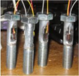
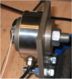
After disappointing performance with commercially available bolt sensors MoreVision devised and produced special test bolts by introducing flats on the shank of the bolts and attaching standard linear gauges (photo on the left). The bolts were calibrated in a laboratory load cell shown in the photo on the right.
BOLT RELAXATION TEST The test bolts were installed on a stationary vehicle in a depot. During installation the load in the bolt was measured as the bolts were torqued up. The bolt force was measured for a number of hours to see if any element in the joint would relax resulting in a significant loss of bolt pretension and premature fatigue failure. The test concluded that relaxation of the joint was within normal acceptable levels and the threat of bolt pretension loss was ruled out. |
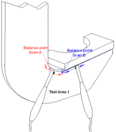
DYNAMIC 'HAMMER' TEST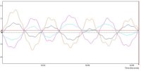 Whilst the the vehicle was stationary in the depot the antennae raft was struck with a rubber hammer allowing the raft to vibrate. The response was also seen by the bolt sensors. A spectrum analysis of the bolt test signals illuminated the frequencies associated with the natural modes of vibration. Closer examination of the phasing of the time signals showed the fundamental 'springboard' mode directly (see plot on left). |
ON-TRACK TESTING
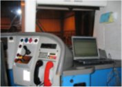
The data acquisition equipment and computer were installed in the drivers cab. A test route of over 200miles was considered representative of normal service. It was even possible for the train to remain in service as the data was acquired which helped the client maintain his train availability and service levels.
POST-PROCESSING OF TEST SIGNALS
1) FILTERING NOISE
When all the train systems were started up in the depot it was noticed that some noise was picked up by the strain gauges. The characteristic of this noise was very high frequency (greater than 500Hz). The hammer test has shown that the predominant structural frequency was less than 50Hz so frequencies of over 200Hz were taken out using software filters.
2) DAMAGE CALCULATION
The filtered signals were the assessed using rainflow counting techniques to reduce the signals to stress histograms. The fatigue life could be calculated from the stress histograms.
CONCLUSION
Local vibrations due to the resonant response of the raft resulted in higher levels of load than was assumed in the design loadcase. This gave rise to a premature bolt fatigue failure.
SOLUTION
MoreVision working together with the depot mechanical engineering team devised an end support bracket for the antennae. MoreVision prepared a finite element analysis justification for the new end support bracket together with revised bolt calculations and the solution was also proven by further on track testing.
Rover Roof Racks

Racking systems have stringent test requirement before they are approved for use on the road. MoreVision analysis methods allowed for far faster design iteration and success rates that was traditionally achieved using a design and test approach.
Cryogenic Road Tanker

MoreVision joined the Design team at M1 Engineering to provide a structural design input when they developed the next generation cryogenic road tanker. The assessment covered the static and fatigue strength of the tank and trailer.
What is LNG and how is it stored?
MoreVision supply analysis services to the gas industry and have undertaken structural analysis to validate the of design of liquid natural gas (LNG) storage facilities.
Structural Analysis:
The lining of a vast concrete tank is required to provide a vapour barrier for the entire life of the LNG storage facility. Unfortunately concrete shrinks with age and a special cruciform joint was designed by MoreVision so that the lining could accommodate this movement. The analysis required a complex large deflection plastic analysis.
Pipework Stress Analysis:
Stresses in pipes and pipe attachment points are assessed against the requirements of ASME.
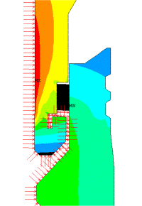
Thermal Analysis:
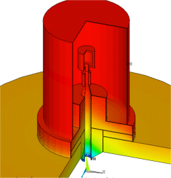
Components are exposed to liquid natural at temperatures down to -160°C. It was necessary to build thermal models to check the effectiveness of the heat break designs and determine the temperature distribution throughout the tank roof equipment. This was required to ensure that the operational temperature limits of constituent parts are not exceeded or to determine the need for safety guards to protect personnel from extreme heat (or cold).
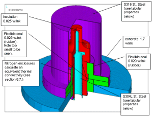
Typically model includes boundary temperatures, heat fluxes, the relevant conduction properties, convection surface details and radiation surface details.
ANSYS Script Generators
Often a large number of items require assessment and Morevision have developed ANSYS script generators to speed up the process of assessment. Most of the finite element models could be reduced in size by taking benefit of axi-symmetry and the time to complete an analysis was remarkably fast.
How did Alaska Airlines Flight 261 Fail?
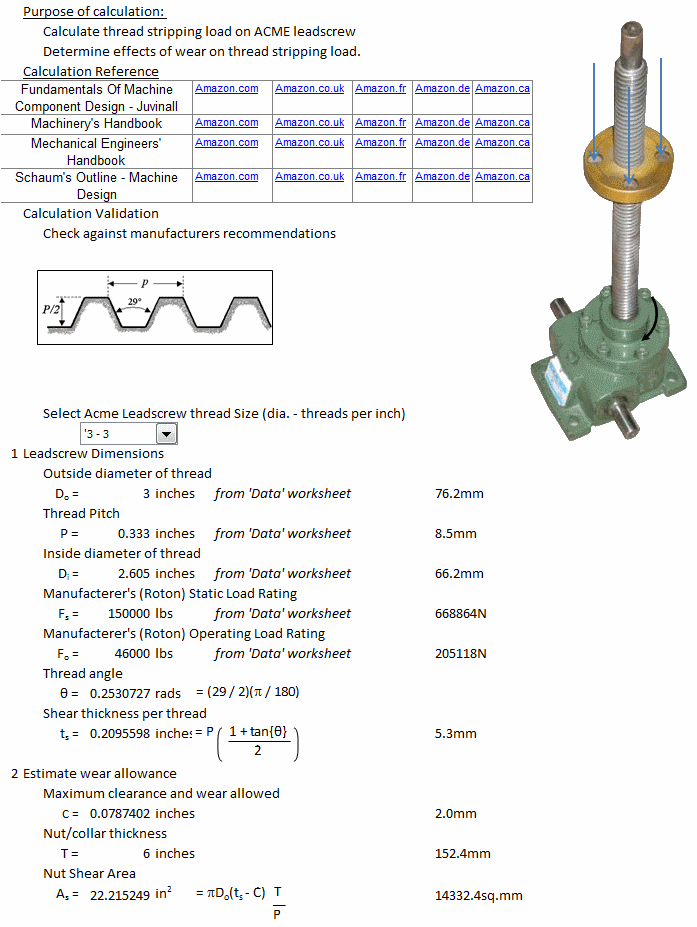
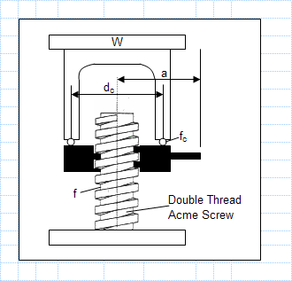
A jackscrew (or screw jack) is a type of jack you will have probably seen stowed in your car but they are used extensively in other mechanical devices. They operate by turning a leadscrew to produce linear motion of a ‘load-nut’. An acme thread form is most commonly used, as this thread is very strong and can resist the large loads imposed on most jackscrews. Jackscrews are self-locking, which makes them intrinsically safer than other jack technologies like hydraulic actuators which require continual pressure to remain in a locked position. However if not lubricated they can be dramatically weakened through wear. One of our failure investigations concerns such a failure of a jackscrew device. We are bound by confidentiality agreements from publishing details of the investigation but whilst researching another more prominent and more widely reported incident was discovered. This incident had far more devastating consequences but featured an identical failure mechanism to the one we are studying.
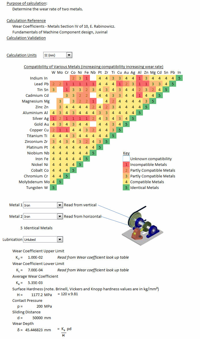
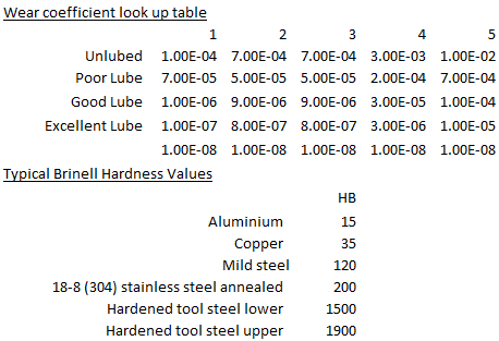
ExcelCalcs Repository Calculation 1 - As is our practise we publish any calculations that might be useful to other engineers on the ExcelCalcs site. Clearly we do not publish any confidential information but in the course of our work we produce generic calculations that are likely to be useful for future problems, these we upload to ExcelCalcs. One such calculation determines the adhesive wear rate of two metals which we can apply to our jackscrew investigation. It employs some data published in “Wear Coefficients - Metals Section IV of 10” by E. Rabinowicz and “Fundamentals of Machine Component Design” by Juvinall. It considers the compatibility of various metal combinations. Materials with increased levels of compatibility have an increased tendency ‘weld’ together and a higher wear rate. It also considers the hardness of the material and the contact pressure between the two materials. Reflecting on the incident it is unlikely that unsuitable materials were selected but it is possible that pressure on minimising weight resulted in selection of a smaller leadscrew operating under high contact pressure and a correspondingly high wear rate.
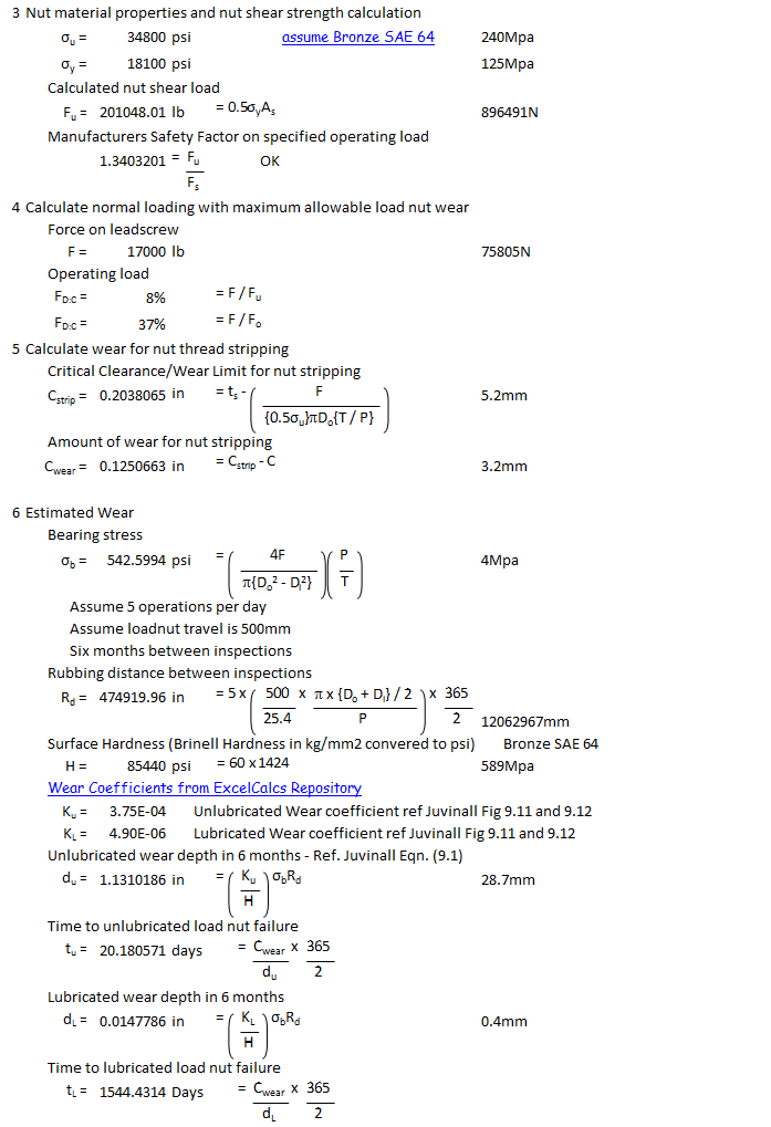
ExcelCalcs Repository Calculation 2 - A second calculation in the repository considers the strength of jackscrew load-nuts and how the strength of the load-nut reduces as it wears. What is particularly interesting is the difference between the wear rates on a lubricated jackscrew are almost 100 times lower than an un-lubricated one. The calculation is a very useful to set an inspection intervals to ensure that un-lubricated jackscrews will be identified before it leads to a failure. Using the calculation you can identify the most important parameters to decide the best way to enhance the safety of your designs.
The calculations sadly makes it all too clear to see how inadequate maintenance and poor lubrication led to excessive wear and catastrophic failure aboard Alaska Airlines Flight 261.
Subsea Equipment Assessment of Trawler Snagging Loads:
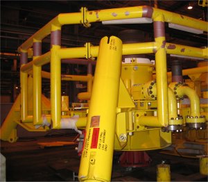
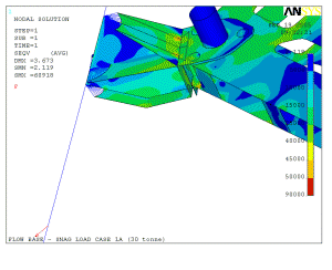
Sub-sea oil equipment may be snagged by fishing trawler nets. Our assessment considered if the equipment was capable of withstanding such loads. Forces on the leg joint to the main structure was stressed beyond yield but the analysis showed acceptable levels of plasticity and the permanent set in the leg.
Sleeve Analysis:
These analyses consider one concentric part within another. Its is possible to make use of axisymetric models which allows for very detailed modelling without a massive computational effort. Often it is necessary to use contact elements as an inner part subject to a high internal pressure may expand and be supported by the external part. Sometimes the analysis is used to consider the performance of a seal as each part deflects.
Pipe Stress Analysis:
Stresses in pipes and pipe attachment points is considered to the requirements of ASME.
Valve Stress Analysis:
Valves are subject to enormous pressures, this analysis ensured that stresses remain within the limits prescribed by ASME III.
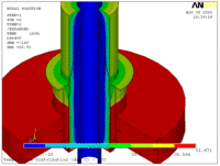
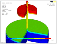
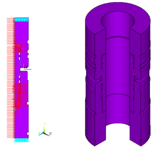
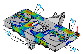
Pump Casting Fracture Analysis
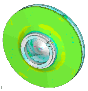
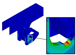
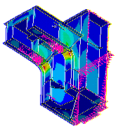
A pump manufacturer wanted to know what size of crack/defect would be acceptable in his impeller castings. As the impeller is spun round at very high speeds giving it becomes subject to radial and hoop stresses. MoreVision prepared a finite element model (shown opposite) to study the stress distribution. The finite element stress predictions were verified by classical hand calculations.
Fracture mechanics calculations were then prepared to determine acceptable flaw sizes for both surface defects and embedded defects. This enabled an inspection criteria to be established which would reduce the amount of reject material and increase the security of knowing that all those entering service would not fail as a result of fast fracture.
Flywheel Analysis
This investigation considered how much material could be safely removed during a refurbishment of a flywheel. Consideration was given to static strength, out of balance forces and fatigue strength.
Wind Turbine Hub

MoreVision helped Taylor Woodrow Wind Energy Group design the hub of a horizontal axis wind turbine. This was the critical structural item on the wind turbine.
 MoreVision has a particular expertise in the structural design of construction equipment. We provide the "Design of Construction Equipment" course to leaders in the industry. We have devised new methods of assessment for our clients and invested in software to speed up the assessment procedure. This software is available for use and/or modification as required by new contracts.
 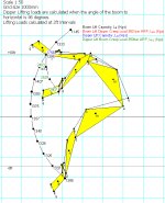 Kinematics Analysis of an Excavator Arm:
MoreVision built a mathematical model of complete vehicles (see our excavator arm example ). The model could calculate any geometrical configuration of the excavator arm. Digging and dipping forces would be calculated for each geometric configuration. The model calculated geometry envelopes, digging force envelopes and lifting force envelopes. The performance of competitor machines could easily be assessed and compared on a like for like basis because the model was fully parametric.
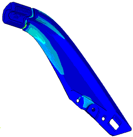
 Assessment of a Loader Arm:
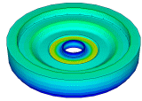
MoreVision developed an ANSYS script to generate a simple beam model of a loader and chassis which could be positioned in any geometric configuration (loading position, raised position etc.). The model was used to determine free body forces acting on each component in the machine (Chassis, arm, links, rods and buckets). The free body forces could be extracted from the beam model and applied to a detailed solid finite element model of each component (the picture opposite shows the arm component). The solid models were used to perform a detailed static strength and fatigue strength checks. A non-linear plastic analysis of this arm was also performed for an overload case to determine the permanent and magnitude of residual stresses.
 Claas Teleporters:
Claas had acquired a business which manufactured telehandling vehicles. Traditionally telehandling vehicles have been designed without any particular structural design methodology. MoreVision were commissioned to develop a structural design performance specification for the vehicle, this included the telescopic arm and the vehicle chassis. Subsequently a full static and fatigue assessment against the specification was undertaken and a summary of design change recommendations were delivered to the client.
MoreVision have undertaken many crane assessments using UK and European standards. In addition they have also undertaken seismic assessments of high integrity cranes.
Code Assessment of Cranes
MoreVision have software and ANSYS scripts for crane assessment in the UK (BS2573) and in Europe (DIN 15018).
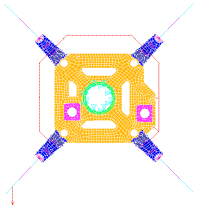
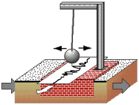
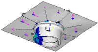
Seismic Assessment of End Carriage
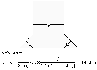
Some assessments have involved seismic analysis of cranes and other mechanical equipment for British Nuclear Fuels. The sketch opposite shows how a seismograph works but is also useful to show how a structure would be loaded during a seismic event. The model aboveshows a zoom in plot on a crane crab end frame. The work was undertaken to perform a detailed fatigue assessment of the end carriage. A number of checks were required by the design code (BS2573) but this was made simple by writing ANSYS scripts so that the checks could be automatically evaluated. Apart from the normal code requirements this high integrity crane required seismic loadcases to be assessed. Weld throat strength and fatigue strength was checked outside of ANSYS using software from the ExcelCalcs Repository.
 Fatigue assessment of rollercoasters. |
 Bruce's articulated head at Disneyland Paris. |
 Pinned articulated joint in wagon at Disneyland Paris. |
 Pinned joints on the London Eye dummy pods. |
Building and managing a theme park is clearly focused on visitor safety. MoreVision are often called to assess the strength, fatigue strength and safety of new attractions.
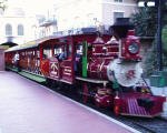
The Hong Kong Disneyland Railroad Vehicles
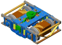

The Hong Kong Disneyland Railroad vehicles carry guests between attractions on the resort and requires extensive analysis to satisfy the local regulatory bodies. The train comprises a loco, tender vehicle and coaches. Each vehicle has its own bogie and wheelsets and all items of equipment required assessment. Finite element analysis and calculations considered the static strength and the fatigue strength of the railroad vehicles. Analysis covered many combinations of vertical loads (tare to crush), longitudinal loads (braking, vehicle recovery) and transverse loads (curving, wind and slope). MoreVision worked closely with the vehicle manufacturers transferring data via the internet. MoreVision gave further support by assisting in the client design scrutiny process.

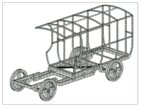
Static strength and fatigue strength analysis was required for the Main Street Vintage Vehicles in Disneyland's new Hong Kong Resort. These included a paddy wagon and a double deck omnibus vehicle.
 MoreVision have done a great deal of railway bodyshell analysis but analysis for the Theme Park industry is actually more like crane design than railway design. MoreVision prepared calculations for TUV approval using German DIN standards. MoreVision were also required to take the calculations through the client scrutiny process.
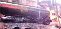
The picture above shows Disneyland's 'Catastrophe Canyon' ride. A burning petroleum tanker about to falls onto a crowd of onlookers... a job for Superman? No MoreVision! We undertook a loading analysis and a stress and fatigue assessment of the wagon kingpin joint to ensure spectator safety.

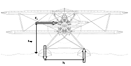 Remember when Indiana Jones escaped a band of marauding natives by swimming to his bi-plane floating of a river. Disney wanted to recreate the feel of the film and bought a identical plane for use in their 'Indiana Jones and the Eye of the Temple' attraction. These planes have a take off speed of 30 miles per hour so the problem given to MoreVision was to stop the plane from taking off in strong winds. We undertook some aerodynamics calculations and designed an anchorage system for the plane.
Pinned hold down connection for Indiana Jones's bi-plane at Tokyo DisneySea.
A market stall cart conceals a giant airbag to break the fall of a stunt man. It was particularly difficult to design a light weight but rigid frame.
|
Consultancy Projects... |
Consultancy Projects - Fatigue Analysis Of Welded structures
|
Our Consultancy Projects - Random Vibration Analysis.") Shock loads to meet IEC61373 (category 1 class A). .") Vibration levels to meet IEC61373 (category 1 class A).  Finite element model.  Frequency assessment. ") Calculation of Acceleration Spectral Densities (ASD)  Bolt assessment.  Eurocode 3 fatigue assessment.  View fatigue classification directly on finite element model.  Shake table testing and analysis verification. |
Related Consultancy Work Strength of composite railway vehicle partitions.  Testing of composite panels (see video).  Tram way composite floor study.  Composite panel construction for toilet module.  Dynamic analysis of composite structure.  Rod end investigation.  Thread SCF study  Key slot fatigue study |


.")


Terminology
Local nominal stress: Nominal stress including macro-geometric effects, concentrated load effects and misalignments, disregarding the stress raising effects of the welded joint itself.
Structural stress: A stress in a component, resolved taking into account the effects of a structural discontinuity, and consisting of membrane and shell bending stress components.
Structural discontinuity: A geometric discontinuity due to the type of welded joint, usually found in tables of classified structural details. The effects of a structural discontinuity are (i) concentration of the membrane stress and (ii) formation of secondary bending stress.
Local notch: A notch such as the local geometry of the weld toe, including the toe radius and the angle between the base plate surface and weld reinforcement. The local notch does not alter the structural stress but generates non-linear stress peaks.
Notch stress: Total stress at the root of a notch taking into account the stress concentration caused by the local notch. Thus the notch stress consists of the sum of structural stress and nonlinear stress peak.
Notch stress concentration factor: The ratio of notch stress to structural stress.
Hot spot: A point in structure where a fatigue crack may initiate due to the combined effect of structural stress fluctuation and the weld geometry or a similar notch.
Hot spot stress: The value of structural stress on the surface at the hot spot (also known as geometric stress or structural stress).

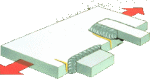
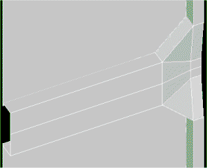
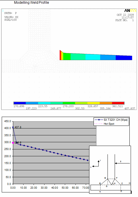
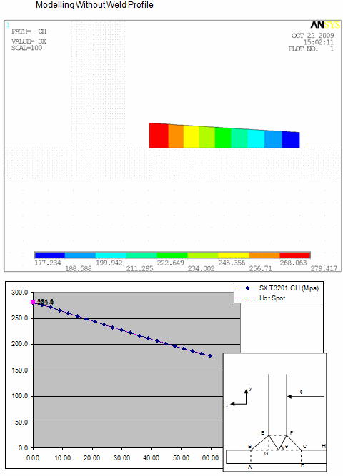
Figure 1 – Hot spot positions a, b and c and explanation of hot spot and notch stresses

Figure 2 – Determine hot spot stress by extrapolation of FE result
Determine Hot Spot Stress for Fatigue Assessment. t is not necessary to model the weld profiles for the following reasons:
• Actual welds may have a variety of profiles and it is not possible to model every variant.
• The SN curve includes the notch effect at the weld toe based on a statistical assessment of a many fatigue tests.
• Inclusion of the weld makes determination of the hot spot stress more difficult to determine. Compare the stress along paths with and without the weld profile modelled.
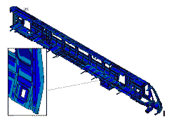
Assessment of the interior of a railway vehicle is required to ensure the safety of passengers, particularly in a crash situation. MoreVision have extensive experience in supplying these calculations in particular for the refurbishment of London Underground's 73 tube stock (shown opposite) and the refurbishment of the Stansted Express. In addition MoreVision supports equipment suppliers in the preparation of calculations for new vehicles.
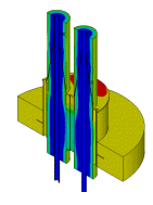
MoreVision has expertise in the analysis of composite honeycomb panel structures. These lightweight materials are commonly used for galley areas, toilet modules, doors and partitions.
The animation opposite shows the first mode of vibration of a ceiling hung steam oven unit made from honeycomb panels (shown transparently to view mounting brackets and body structure). The steam ovens were very heavy and our client was not only concerned about the strength of the honeycomb panels but also the strength of the body structure. Resilient mounting brackets were included to isolate the unit from high frequency vibrations to reduce noise levels in the galley.
 Interior Doors, Partitions and Luggage Stacks. The picture opposite shows a finite element model of a full wall partition with a central door and two luggage stacks. It is constructed from composite honeycomb material, glass, aluminium and steel. The assembly included a number of bolted and riveted joints. The model was used for a static strength and fatigue strength check.
Another relatively simple analysis but the strength of the table could be very important in a crash situation
Toilet modules will contain walls, doors and various pieces of equipment that each require assessment.
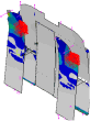
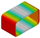
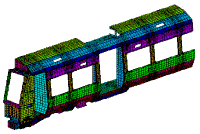
This crashworhiness assessment considered re-engineering the front end of a leading vehicle in a train to improve vehicle crash performance. The study provides an interesting comparison between a vehicle with no provision for crashworthiness (unmodified) and one with a 2MJ collapse structure on the leading vehicle (modified). Which train would you rather be in? The top one or the bottom one? Now play the video and see for yourself the benefits of the designing for crashworthiness. The article outlines the calculations for the train end crash structure. It considers kinetic energy and its conversion to strain energy and compares resulting forces and deceleration rates of the two trains.
Video Clip
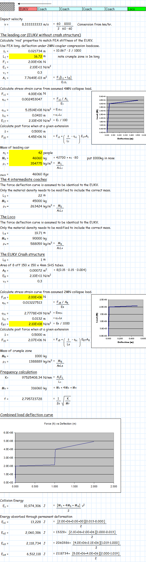
Figure 2 - Basic Energy Calculations
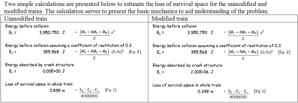
Figure 3 - Velcocty vs Time

Figure 4 - Impact Force vs Time
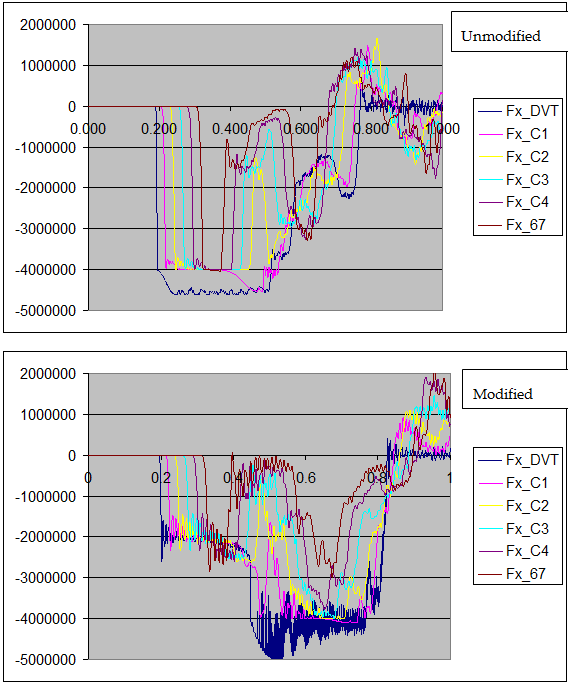
Figure 5 - Acceleration vs. Time

Figure 6 - Summary
The detail
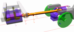
The 1D Analysis Model - This analysis considers GM/RT 2100 Issue 4 crash scenario 1 (similar trains impacting with a closing speed of 60kph). A dynamin model has been developed for this crash assessment. To maintain client confidentiality the vehicle is referred to as the EUKV. The loadcase starts when the train is travelling at 5m/s and is 2m away from the wall. Initially a time step of 10ms was considered over a period of 3 seconds. Finally the analysis was re-run with a time step of 1ms over the first second (as the impact is pretty much over within this time).
Determine the Model Parameters - The calculation above determines the material properties that are assigned to the LSDYNA elements to model the mass and crush behaviour of the EUKV, coaches and loco (driving the train forward from the rear - see Figure 1).
Basic Energy Calculations - The model parameters and verification calculations are set up using Excel (see Figure 1). The script for model generation and initial conditions is generated from the Excel worksheet too so that a number of scenarios could be quickly assessed.
The natural frequency of the train vibrating as a rod is calculated because this can be observed in some of the time history plots in the results section (see Figure 1). The train travels 0.2 s before impact with the wall, the structure deforms during the impact and then recoils backwards vibrating at this frequency. The combined load defection characteristic of the complete train is easily constructed from its constituent parts. The plot above shows the load defection characteristic for the modified train which includes the crash structure fitted to the front end of the EUKV. It also calculates the area under the curve for each straight line segment (i.e. the energy absorbed). It is interesting to note that only small amounts of energy are absorbed by the elastic deflections and the majority of the absorption occurs when the structure plastically deforms. Once the crash structure is fully collapsed the main structure begins to be plastically deform with the resulting loss in survival space for passengers and increase in compression loads.
Two simple calculations are presented below to estimate the loss of survival space for the unmodified and modified trains. The calculation serves to present the basic mechanics to aid understanding of the problem (see Figure 2).
Results - The results are presented first for the unmodified EUKV and then the modified EUKV.
Velocity - Figure 3 compares the velocity (m/s) vs. time. The train travels at 5m/s for 0.2 seconds before the front of the EUKV strikes the wall. You will observe the short time interval as the shock wave travels down the train and each of the cars in turn begins to decelerate. The train recoils from the wall at about 1.5m/s vibrating as it does so (note the resonant frequency can be observed - see calculation in section 0). The impact is more or less complete for both the unmodified and modified trains in less than 1s.
Impact Force - Figure 4 compares compression force levels (N) vs. time. In the unmodified vehicle the impact force quickly rises to the 4MN level when the cars begin to collapse. As the shock wave travels down the train and each car sees the compression load a fraction of a second after the car in front. When the modified vehicle strikes the wall compression loads are initially limited to 2MN until the crash structure completely crushed after about 0.4s and then the load rises to the 4MN level as the cars then begin to collapse.
Acceleration - The net force on each car is calculated from the force information and the mean acceleration obtained by dividing by the mass of the car. This information is presented in Figure 5. prEN 15227 requires that accelerations are limited as far as practical to 5g and should not exceed 7.5g. It concedes that it will usually be necessary to accept higher levels of acceleration in the cab but only as transients lasting less than 5ms.
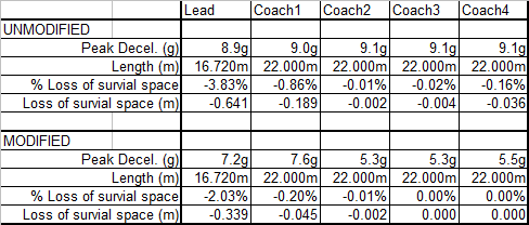
In the unmodified vehicle acceleration levels peaks at 9.1g and is consistently greater than 7.5g for time periods longer than 5ms. Thus it does not comply with the requirements of prEN 15227.
The modified vehicle shows significantly reduced acceleration levels rising to a peak of 7.6g but generally less than 5g. It is interesting to note that the peak 7.6g acceleration occurs at the point where the crash structure is fully collapsed and the carbody begins to collapse. The peak acceleration is greater than 7.5g for just 3.5ms thus the modified vehicle meets the requirements of prEN 15227.
Survival Space - prEN 15227 also requires that the loss of survival space shall be limited to 1% of the initial lengths. prEN 15227 also requires us to consider both passenger and crew survival spaces. The un-modified EUKV may carry train staff. The loss of survival space is compared for the un-modified and modified EUKV in Figure 6.
The un-modified EUKV shows a 0.641m loss of survival space (3.83%) failing the prEN 15227 criteria. The loss of survival space in the coaches is less than 1%. The total loss of survival space for the whole train is 0.879m which compares well with 0.899m estimated in the Excel calculations.
The crash structure in the modified EUKV is entirely crushed but the survival space is reduced by only 0.339m (2.03%). Most of this is lost towards the front of the EUKV. Clearly this has implications for the driver but his cab is rigid compared to the structure in the cab door area. This means that the driver’s survival space will be retained at the expense of the cab doorway structure. Immediately behind the cab is an equipment area with no passengers or crew. It is likely that most of the loss of survival space will occur here nearer the front of the vehicle rather than the passenger saloon area in the rear. The loss of survival space in the passenger saloon (final two thirds of the vehicle) is likely to be less than 1%. The loss of survival space in the coaches is less than 1%. It is concluded that the modified EUKV will pass the prEN 15227 survival space criteria. The total loss of survival space for the whole train is 0.386m which compares well with 0.399m estimated in the Excel calculations.
 Input: Drawings supplied in PDF format by email. Input: Drawings supplied in PDF format by email. |
 Deadline: Three weeks after purchase order. Deadline: Three weeks after purchase order. |
 Output: Deveop strategy with the client assess a number of impact scenarios and prepare final calculation report suitable for third party scrutiny. Output: Deveop strategy with the client assess a number of impact scenarios and prepare final calculation report suitable for third party scrutiny. |
 Given our experience in structural calculations for the railway industry the class 222 project team asked MoreVision to head up the structural design validation process and support them through the Vehicle Acceptance Body design scrutiny process. The whole project involved the co-ordination of project engineers and subcontractor organisations to produce 75 document packages covering the vehicle interior and externally mounted equipment. Initially a guidance document was written and sample documents circulated so that subcontractor has a clear idea of what was required. As documents were supplied an audit process was established which raised over 500 scrutiny comments. Each comment was closed out individually and the document package was submitted to the Vehicle Acceptance Body. The activity was controlled using a database system and reported to the project director on a month by month basis until all documents had been accepted. Typically we would spend one day every fortnight at the clients premises in Belgium to report progress and discuss issues with each system engineer.
 It is always late on Friday afternoons when something fails, or
something is manufactured incorrectly, or some accident happens. We
can't tell you why it is always Friday afternoon but at MoreVision we
are well practised at working into the weekend to ensure that a
situation is made safe in the short term and if necessary devise plans
to ensure that a long term solution. Some cracks were found in the corner of a cross tube which the materials lab had said were formed during the manufacturing process. The cross tubes had been used in a whole fleet of bodyshells and it was necessary to demonstrate to the client that crack growth could not take place when the bodyshells were in service. MoreVision determined the stress levels in the cross tube from the global bodyshell finite element model, then used sub-modelling techniques to determine a detailed stress analysis of the cross tubes. MoreVision's Fracture Mechanics Software was then used to show that there was no danger of the cracks growing in the structure.
It is always late on Friday afternoons when something fails, or
something is manufactured incorrectly, or some accident happens. We
can't tell you why it is always Friday afternoon but at MoreVision we
are well practised at working into the weekend to ensure that a
situation is made safe in the short term and if necessary devise plans
to ensure that a long term solution. Some cracks were found in the corner of a cross tube which the materials lab had said were formed during the manufacturing process. The cross tubes had been used in a whole fleet of bodyshells and it was necessary to demonstrate to the client that crack growth could not take place when the bodyshells were in service. MoreVision determined the stress levels in the cross tube from the global bodyshell finite element model, then used sub-modelling techniques to determine a detailed stress analysis of the cross tubes. MoreVision's Fracture Mechanics Software was then used to show that there was no danger of the cracks growing in the structure.

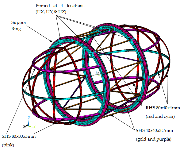
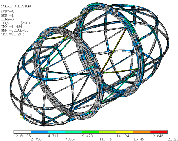
This analysis considered the structural performance of the dummy pod as it moves around the wheel in combination with exceptional wind loads experienced 140m above the ground. The structural assessment of the dummy pod considers the stress in members, the buckling of members, the stress in welded connections and the performance of bolted joints. This article describes a finite element analysis study supported additional calculations which are available for download from the www.ExcelCalcs.com site.

FE Model
Stress in FE Model
Bolt Calculations
Design Code Calculations
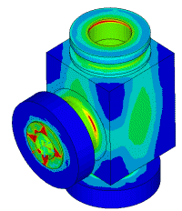
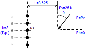
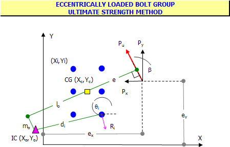
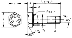
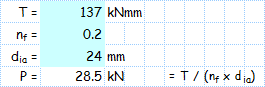
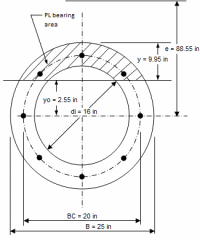
The Detail - The dummy pod is constructed from two end sub-assemblies called thimbles and a central cylindrical sub-assembly called the barrel. The assemblies are fitted to a support ring. A bolt passes through the thimble end plate, through the support ring and through the barrel end ring. 32 M20 bolts per support ring are used around the circumference to connect the parts together. The support ring is fixed in three directions at the pin locations.
An ANSYS finite element model is constructed from beam elements. Stresses are determined by linear elastic analysis and Euler buckling analysis is also performed. There is no particular code of practise applicable to the London Eye dummy pod. BS2573 Part 1: 1983 “Rules for the Design of Cranes” is selected as cranes are mechanical structures subject to wind and self weight loads. It is not a limit state code and requires elastic assessment of the structure. It is similar to BS449 in its methodology. The basic allowable stress is 60% of the material yield (unless limited by buckling considerations). A fatigue assessment is not considered necessary due to the low number of cycles. The model has assigned the material density of steel multiplied by 1.2 as an impact factor. All material is S355 steel with a yield stress of 355MPA. A number of load combinations were considered.
How to read ANSYS plots: The “STEP” number (and “TIME” number) is a load step (e.g. self weight, wind load…). A “SUBSTEP” is of interest for nonlinear analysis but since this assessment is linear elastic so it is not relevant in this case. “SEQV” indicates that we are plotting equivalent stresses (or Von Mises Stress) in MPa. For beam elements SEQV is the addition of the axial stress and the bending stress in two planes. The stress is displayed at all points around the beam section. SEQV indicates the stress magnitude but not the sense (compressive or tensile). “SMN” gives the lowest value of SEQV in the plot and “SMX” shows the highest value. The stress legend shows how colours can be related to the value of equivalent stress in the plot. “DMX” is the maximum vector displacement in the model (in mm).
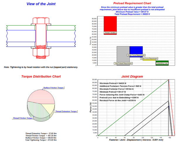
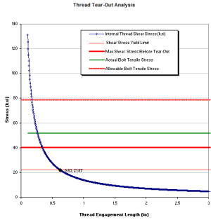
The worst axial force and the worst shear force are incorporated into a
detailed bolt assessment. The calculations check the following:
1) The joint axial strength.
2) The joint preload is sufficient to withstand the applied shear load even after embedding losses and bolt relaxation.
3) The tightening torque requirement.
4) The joint force diagram.
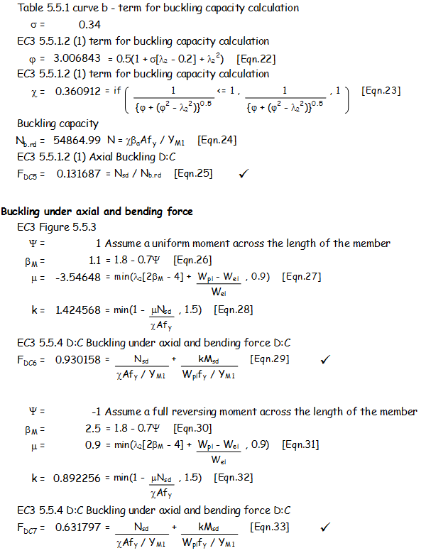
Eigenvalue buckling analysis can be performed by ANSYS. Eigenvalue buckling analysis predicts the theoretical buckling strength (the bifurcation point) of an ideal linear elastic structure. This method corresponds to the textbook approach to elastic buckling analysis: for instance, an eigenvalue buckling analysis of a column will match the classical Euler solution. However, imperfections and nonlinearities prevent most real-world structures from achieving their theoretical elastic buckling strength. Thus, eigenvalue buckling analysis often yields unconservative results, and should be used with caution. However if the Euler buckling load shows a large margin it is very unlikely that effect of real world imperfections will compromise the structures resistance to buckling. In addition members are assessed against the requirements of Eurocode 3.
| Input: Preliminary drawings supplied by client. |
Deadline: Two weeks after purchase order. |
Output: Design change recommendations and a calculation report for final design suitable for third party scrutiny. |
|
Get the Most Out Of Your Test Data.
|
|
Rainflow Counting.
|
|
Spectral
Analysis |
|
Filtering |
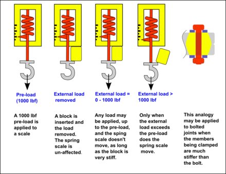
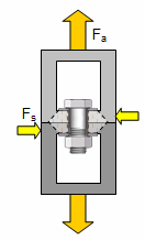
Bolted joints are one of the most common elements in construction and machine design yet they are the root cause of half of the failures investigations undertaken by MoreVision. Every engineer experiences some difficulties with bolts at some point in his career. So what typically goes wrong and what can we do to prevent bolt problems? Follow our bolt failure checklist and find calculations to help you.
 Bolt bench test using a loadcell.  Determine torque-tension relationship by test.  Tapped bolted joint bench test.  Strain gauged bolts for on-site testing.  Installation under a railway vehicle.  Harmonic anlysis of test results  Bolt thermal analysis  Random vibration analysis  Junkers vibration test.  Bolt load analysis  Automaton hold down bolts |
Bolt Investigation Techniques
The ‘simple bolted joint’ can be anything but simple. MoreVision and BoltScience offer a unique skill set to solve your bolting problems. Please contact John Doyle if you require our assistance with your own bolt problems.
Our Consultancy Services – Email all the joint details (bolt specification, clamped materials, tightening procedure, applied axial and shear forces, temperature) and using our databases and analysis tools we’ll produce a report which identifies any area of risk. Maybe you would just like an independent review of your bolting procedures? Bolt Loading Assessment – Not entirely sure what loads your joint will be subjected to? If classical calculations are not enough we use finite element analysis to calculate the loads to which a bolt is subjected. Analysis methods available to us are inertia load assessment, dynamic load assessment, random vibration assessment, thermal assessment and fatigue assessment. Bolt Lab Test – Send us your bolt and in addition to the bolted joint design check report we’ll measure the torque tension relationship for your joint using load cells. Bolt Value Engineering – We help clients replace expensive custom made bolts with cheaper alternatives with no loss in structural performance. Our last value engineering exercise save one of our clients over 1 million dollars. On Site Bolt Testing – If your joint is too big to send to us we’ll come to you. It may be appropriate to use pre-calibrated strain gauged bolts which we can specially prepare for you. Our last test involved monitoring bolts on a railway vehicle. Our measurements were linked to Google Earth via a GPS to that we could identify parts of the railway infrastructure which gave rise to high bolt loads. Bolt Failure Investigations – Ask our team for an independent failure investigation. Our combined bolting experience and analysis tools and skills places you in the strongest position to investigate the root cause of bolt failure. Given the nature of bolt failures this service is offered on an independent and confidential basis.
|


|

MoreVision has a particular expertise in the structural design of railway rolling stock and running gear. Being active in railway industries from across the globe we have a good perspective on all the various standards used in different countries and on different vehicle types. MoreVision services are used by rolling stock manufacterers and operators alike heading failure investigations and supporting engineering teams. MoreVision has been invited on a number of occasions to present papers at the Institute of Mechanical Engineers including "Crash Design of Steel Bodyshells for Virgin" and "The Future of Railway Vehicle Design"

Railway Bodyshell Design
|
MoreVision were involved from the start of the in the concept design and preliminary calculations of the class 22x bodyshells. Later in the project MoreVision were commissioned by Bombardier to undertake an independent design audit of the Virgin Voyager Bodyshells. They were asked to consider the fatigue design aspects of the bolster, in particular dealing with issues arising from the tilting mechanism. Further support to the project was required in the management of subcontractor supporting calculations. In the final stages MoreVision were asked to prepare and present a paper called "Crash Design of Steel Bodyshells for Virgin" which was delivered at a seminar held at the Institute of Mechanical Engineers. |
Having completed the design of the bodyshell ADtranz commissioned MoreVision to undertake the final analysis runs and preparation of all the reports for submission to the client and approval authority. This bodyshell was particular interesting as it was constructed from a fabricated steel chassis and body ends with sidewalls and roof made from wide body aluminium extrusions. The sub-assemblies were bolted together to form the complete bodyshell. Analysis included a static strength assessment, fatigue strength assessment and bolted joint assessment for each of the bodyshell types. |
|
|

 MoreVision
have undertaken design work in Europe, for example the structural design of AM96
Electrical Multiple Units and I11 coaches for BN, SNCB Belgium.
MoreVision
have undertaken design work in Europe, for example the structural design of AM96
Electrical Multiple Units and I11 coaches for BN, SNCB Belgium.
 A
generic rail vehicle may be sold to a number of different
clients.
Each client have their own particular preference for seating
layout.
This means that the positions and sizes of doors and windows
change
between each order. MoreVision have parameterised this
problem so
that once window and door sizes have been defined a program
which automatically generates a finite element model. In this way any
problems regarding resonance, strength of fatigue strength
of the
bodyshell can be understood during the project definition
and
tendering stage. The program even produces a bill of
materials for
tendering purposes.
A
generic rail vehicle may be sold to a number of different
clients.
Each client have their own particular preference for seating
layout.
This means that the positions and sizes of doors and windows
change
between each order. MoreVision have parameterised this
problem so
that once window and door sizes have been defined a program
which automatically generates a finite element model. In this way any
problems regarding resonance, strength of fatigue strength
of the
bodyshell can be understood during the project definition
and
tendering stage. The program even produces a bill of
materials for
tendering purposes.
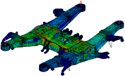
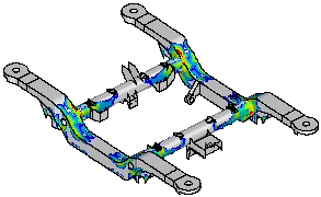
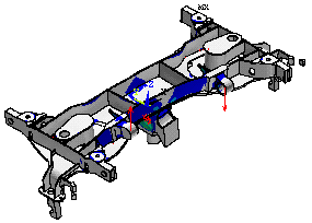
Bogies, Trucks and Adapters
MoreVision works very closely with its client partners. Typically models are supplied by the client by email and Morevision are asked to undertake the static and fatigue assessments and prepare the reports for submission to the end client. MoreVision has developed a number of programs to post-process finite element results which help to reduce the cost of fatigue assessments.
|
Non-Tilting Bogies for Virgin - The bogie is used on the non-tilting Virgin Voyager vehicles. |
Tilting Bogies for Virgin - The bogie is used on the tilting Virgin Voyager vehicles. |
|
Bolster Adapter for Double-Deck Bodyshell - This is a half model of an adapter for a double-deck bodyshell. The vehicles are for use in France so two fatigue assessments were performed to show that is compliant with UK and French fatigue standards. The methods of assessment are completely different. |
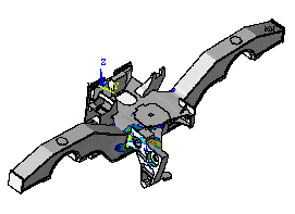
Caracas Bogie - This is a half model of bogie which in in service in Caracas in Venezuela. |
|
M6 Bogie Adapter - The M6 vehicles are for use in France so two fatigue assessments were performed to show that is compliant with UK and French fatigue standards. The methods of assessment are completely different. |
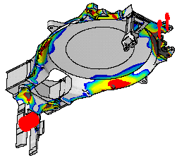
Bolster Adapter for Tilting Train - Bogies are attached to the bodyshell via adapters. design of the adapter is often just as extensive as the design of the bogie. This particular adapter is further complicated due to the tilting mechanism on the train. |
What is so special about Railway wheels?
What is resonance?
|
BEFORE DYNAMIC ANALYSIS TECHNIQUES |
|
HOW CAN A DYNAMIC ANALYSIS HELP ME? |
/p>
MoreVision has developed a number of programs to post-process finite element results, calculate fatigue damage and to plot damage directly onto the FE mesh. The assessments cover code of practices used in many countries (UK - BS7608, US - AISC LRFD, France -UIC 515-4 Goodman Diagram, German DIN 15 018, Swedish Volvo standards)
|
Fracture Mechanics
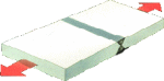
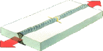
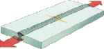
The fatigue life of a welded structure it totally dependant upon the choice of welded detail. In the following examples the detail on the left hand side of the page is improved by adopting the detail on the right hand side. Just three examples are given though there are generally many ways of optimising a fabricated structure.
1) Weld reinforcement and weld toe re- profiling
2) Removal of weld stop starts
3) Do not weld on plate edges
|
Consultancy Projects - Fatigue Analysis Of Welded structures
|
 If a component is
subject to repeated applications of structural loading then it will be
susceptible to fatigue failure. Stresses act on small flaws inherent
in the material causing then to grow until they break. Two approaches
can be employed to assess this situation:
If a component is
subject to repeated applications of structural loading then it will be
susceptible to fatigue failure. Stresses act on small flaws inherent
in the material causing then to grow until they break. Two approaches
can be employed to assess this situation: