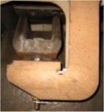
The structural failure of a traction motor mounting bracket occurred in service. Fortunately the motor was prevented from falling onto the tracks by a cardan shaft protection ring thus preventing a catastrophe but the issue was taken very seriously by our client and was quickly elevated to the executive level. The animation shows how the vehicle mounted traction motor drives a cardan shaft which drives the wheels via a bogie mounted gearbox. MoreVision was brought in by the executive engineering managers to devise and implement a technical strategy that would guarantee that no further bracket failures would occur in service. This project covered a period of some 18 months working very closely
with the vehicle manufacturer, the service providers, depot staff and
test sub-contactors.
Our brief was simply:
• to determine risk mitigation actions to keep the fleet working in service.
• to develop a long term 'safe-life' solution.
Initial Analysis
Within hours we began to gain an understanding of the problem using a simple finite element model. This showed that the bracket was particularly susceptible to lateral loading. We gained enough understanding of the bracket fatigue prone areas to position number of strain gauges for an investigative on track test.
Initial On-track Testing
The test train was taken onto the track in a number of configurations (cardan shaft attached, removed and freewheeling). This would help us determine the relative magnitudes of possible fatigue mechanisms. A spotlight was quickly thrown on the importance of low magnitude but high frequency stresses arising from cardan shaft's out of balance forces. This problem could only get worse with time as the cardan shaft wears.
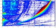
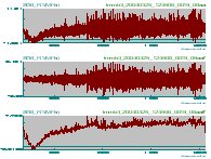
The problem was exacerbated by the dynamic response of the motor rubber mounts whose resonant frequencies coincided with typical line running speeds. The waterfall plot above shows the strain results in the frequency domain (response is plotted against frequency [x] and speed [y]). It shows the maximum response at the same frequency as the cardan shaft rotational frequency. The set of three overlayed curves above shows strain verses time as the train accelerates from 0 to 200kmph. The top graph shows the raw signal (unfiltered); the middle graph shows the high frequency content of the signal (mainly associated with rotation of the cardan shaft); the bottom graph shows the low frequency content of the raw signal (mainly associated with motor torque effects). Both high frequency and low frequency signals had an influence on fatigue life of the bracket. On-track testing helped us to:
- understand the most important fatigue driving mechanisms.
- understand the importance of cardan shaft loading and the dynamic response of the motor on its resilient rubber mounts.
- determine stress signals for input to crack growth models. This forms the basis of an inspection regime to guarantee passenger safety.
- redefine new loadcases to develop a long term solution.
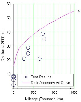
Until a long term solution could be devised and implemented it was necessary to undertake risk mitigation actions to ensure the the fleet was running without any risk to passengers safety. This was possible by establishing a crack inspection regime. Ultra-sound Inspection trials were set up to determine the minimum detectable crack size. Simultaneously, using samples of stress measured during the on-track testing and incorporating stress factor to account for cardan shaft ageing, it was possible to calculate an inspection interval to guarantee detection of a crack before a bracket failure.
Further Risk Mitigating Actions
The safety of the fleet was increased further by introducing a polished weld toe detail. This improved the situation in the following ways:
- it removes weld toe material (this is inherently poor quality material with many defects and flaws that make it susceptible to fatigue failures).
- it repositions the maximum stress away from poor quality weld material and into good quality polished parent material. Thus the initiation of crack growth was less likely.
- it increases inspectability of the bracket (smaller cracks could be reliably detected thus cracks can be repaired sooner and the safety of the fleet is increased).
It was difficult explaining that removal of material from a critical section would result in a fatigue strength improvement but the method was endorsed by supporting finite element analysis and expert papers. The detail was easily and quickly introduced by a drilling and polishing operation.
Moitoring the Fatigue Regime
Joints in the cardan shaft wear with time and increase the amount of out of balance force acting on the traction motor mounting brackets. Our analysis and calculations showed that we needed to decrease the inspection interval to accounted for an ever increasingly aggressive fatigue environment. It was important to monitor the cardan shaft loading by continuous testing of cardan shafts on a balancing machine. The problem was exacerbated when a new risk due to heat damaged rubber motor mounts was identified. Additional stress factors were introduced to account for the new risk and the inspection period was reduced accordingly. Over the monitoring period the inspection regime managed to find a number of cracks which were safely repaired before they became anywhere close to the critical size for fracture of the bracket.
Dynamic Analysis
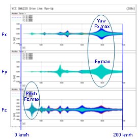
A non-linear dynamic model was developed by a partner in Switzerland to study the dynamic behaviour of the traction motor on its resilient mounts excited by the cardan shaft out of balance forces from 0 to 200kmph. Low speed pitching mode gives peak vertical loading on the motor mounting brackets. High speed yaw mode gives peak longitudinal and lateral loading. All modes of vibration are evident in the plot of bracket forces verses speed. It is notoriously difficult to interpret the results of dynamic analysis and define loadcases for a finite element stress model. The initial approach was to take the maximum loads in each direction and apply them in the most adverse combination. This proved to be too conservative and an alternative approach was developed. It was possible to determine stress time histories at fatigue critical locations using dynamic model output. Damage could then be calculated using rain flow counting methods. Once the approach was developed, design iteration which included the rubber mount manufacturer allowed us to optimise the stiffness and damping characteristics of a new high temperature motor mount. This was to become an important part of the solution.
Long Term Solution

A long term solution is developed comprising:
- New 'riveted in' reinforced front brackets.
- Structural enhancements including TIG dressing of weld toes and profiling plates to introduce softener details at weld ends.
- Inclusion of a dynamically optimised high temperature motor mount.
- Cardan shafts monitoring and control system.
The solution was developed using predictive analysis techniques and validated by monitoring critical strain gauge locations over some 20,000km. In addition the predicted benefit of a new high temperature rubber motor mount was also supported by on track testing. The final solution has an unmonitored safe life of 30 years.