DESCRIPTION OF THE FAILURE
As always our approach is to propose solution found through understanding the mechanics of failure. A railway vehicle antennae raft is cantilevered the bogie transom by 4 M16 bolts. The bolts had repeatedly failed in service and was considered a severe hazard as a detached raft could in a worst case scenario derail a train and result in loss of life. MoreVision were invited to investigate the failure. The bolt samples were sent to a metallurgical laboratory and examination of the bolt fracture surfaces showed all the characteristics of a fatigue failure. The bolts were renewed every month as a risk mitigation action until the investigation reported its conclusions. MoreVision initially performed bolt fatigue calculations using the loading assumed in the design case. The calculations did not predict a bolt failure so it was suspected that the actual service loads were greater than that assumed for design purposes. Another possibility was that some element in the bolted joint was relaxing giving rise to loss of bolt pretension and a premature fatigue failure.
DESIGN AND CALIBRATION OF STRAIN GAUGE BOLTS
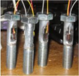
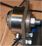
After disappointing performance with commercially available bolt sensors MoreVision devised and produced special test bolts by introducing flats on the shank of the bolts and attaching standard linear gauges (photo on the left). The bolts were calibrated in a laboratory load cell shown in the photo on the right.
BOLT RELAXATION TEST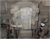 The test bolts were installed on a stationary vehicle in a depot. During installation the load in the bolt was measured as the bolts were torqued up. The bolt force was measured for a number of hours to see if any element in the joint would relax resulting in a significant loss of bolt pretension and premature fatigue failure. The test concluded that relaxation of the joint was within normal acceptable levels and the threat of bolt pretension loss was ruled out. |
DYNAMIC 'HAMMER' TEST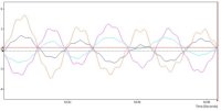 Whilst the the vehicle was stationary in the depot the antennae raft was struck with a rubber hammer allowing the raft to vibrate. The response was also seen by the bolt sensors. A spectrum analysis of the bolt test signals illuminated the frequencies associated with the natural modes of vibration. Closer examination of the phasing of the time signals showed the fundamental 'springboard' mode directly (see plot on left). |
ON-TRACK TESTING
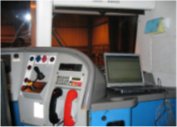
The data acquisition equipment and computer were installed in the drivers cab. A test route of over 200miles was considered representative of normal service. It was even possible for the train to remain in service as the data was acquired which helped the client maintain his train availability and service levels.
POST-PROCESSING OF TEST SIGNALS
1) FILTERING NOISE
When all the train systems were started up in the depot it was noticed that some noise was picked up by the strain gauges. The characteristic of this noise was very high frequency (greater than 500Hz). The hammer test has shown that the predominant structural frequency was less than 50Hz so frequencies of over 200Hz were taken out using software filters.
2) DAMAGE CALCULATION
The filtered signals were the assessed using rainflow counting techniques to reduce the signals to stress histograms. The fatigue life could be calculated from the stress histograms.
CONCLUSION
Local vibrations due to the resonant response of the raft resulted in higher levels of load than was assumed in the design loadcase. This gave rise to a premature bolt fatigue failure.
SOLUTION
MoreVision working together with the depot mechanical engineering team devised an end support bracket for the antennae. MoreVision prepared a finite element analysis justification for the new end support bracket together with revised bolt calculations and the solution was also proven by further on track testing.