
Motorcycle Swing Arm Load Cases for Acceleration, Braking and Cornering
 (4/1)
Description
Motorcycle Swing Arm Load Cases for Acceleration, Braking and Cornering
An Excel workbook that works out the loads on a motorcycle's rear swing arm for three design load cases (accelerating, braking and cornering) and records the finite-element results for three versions of the swing arm. It is a clear worked example of turning vehicle data into the forces you apply to a component model.
Method
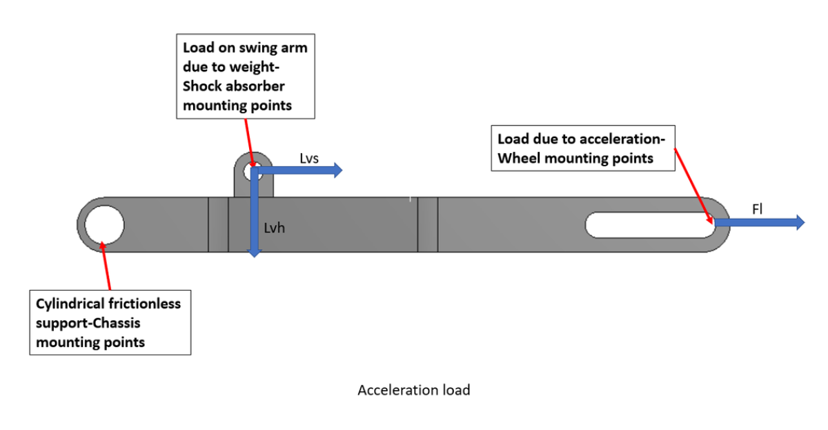
- Static load: the rear-axle share of the bike and riders' mass, (Ms + 2Mp) × X × g, resolved into vertical and horizontal components at the shock absorber angle (46.5°).
- Accelerating: longitudinal force at the wheel mounting = total mass × maximum acceleration.
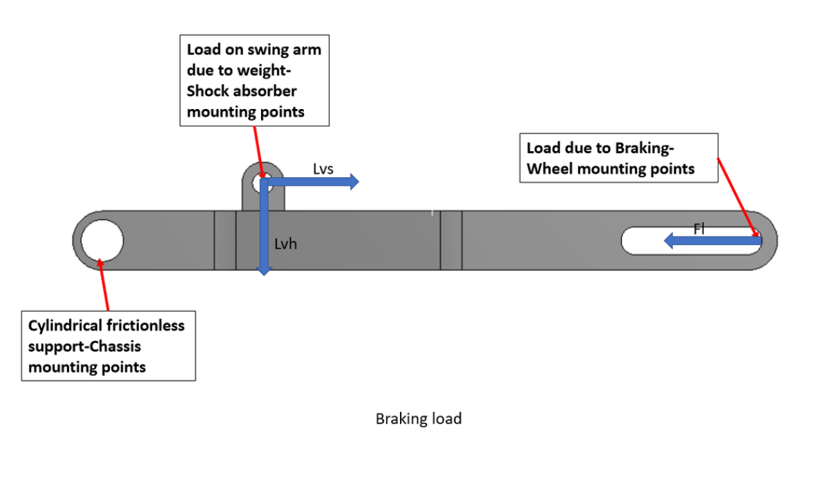
- Braking: deceleration from 100 km/h to rest in the stated time, and the longitudinal force = total mass × deceleration.
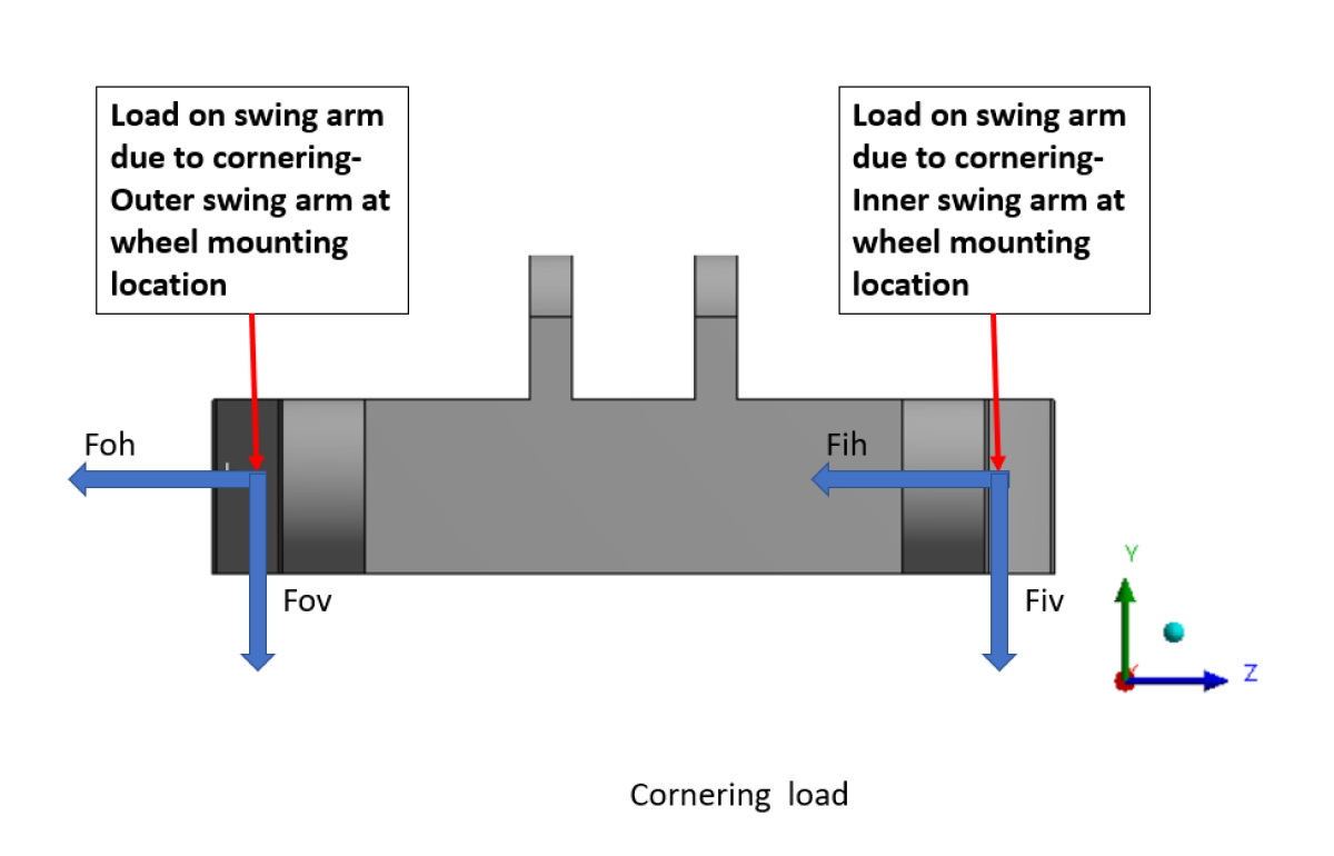
- Cornering: the total weight split between the inner and outer arms (70% and 30%) and resolved at the maximum lean angle (40°).
Inputs
- Motorcycle mass (kg), rider mass (75 kg each, two riders) and the rear-axle weight share
- Maximum acceleration (m/s²) and braking time from 100 km/h (s)
- Shock absorber angle, lean angle and the inner/outer load split
Outputs
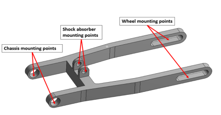
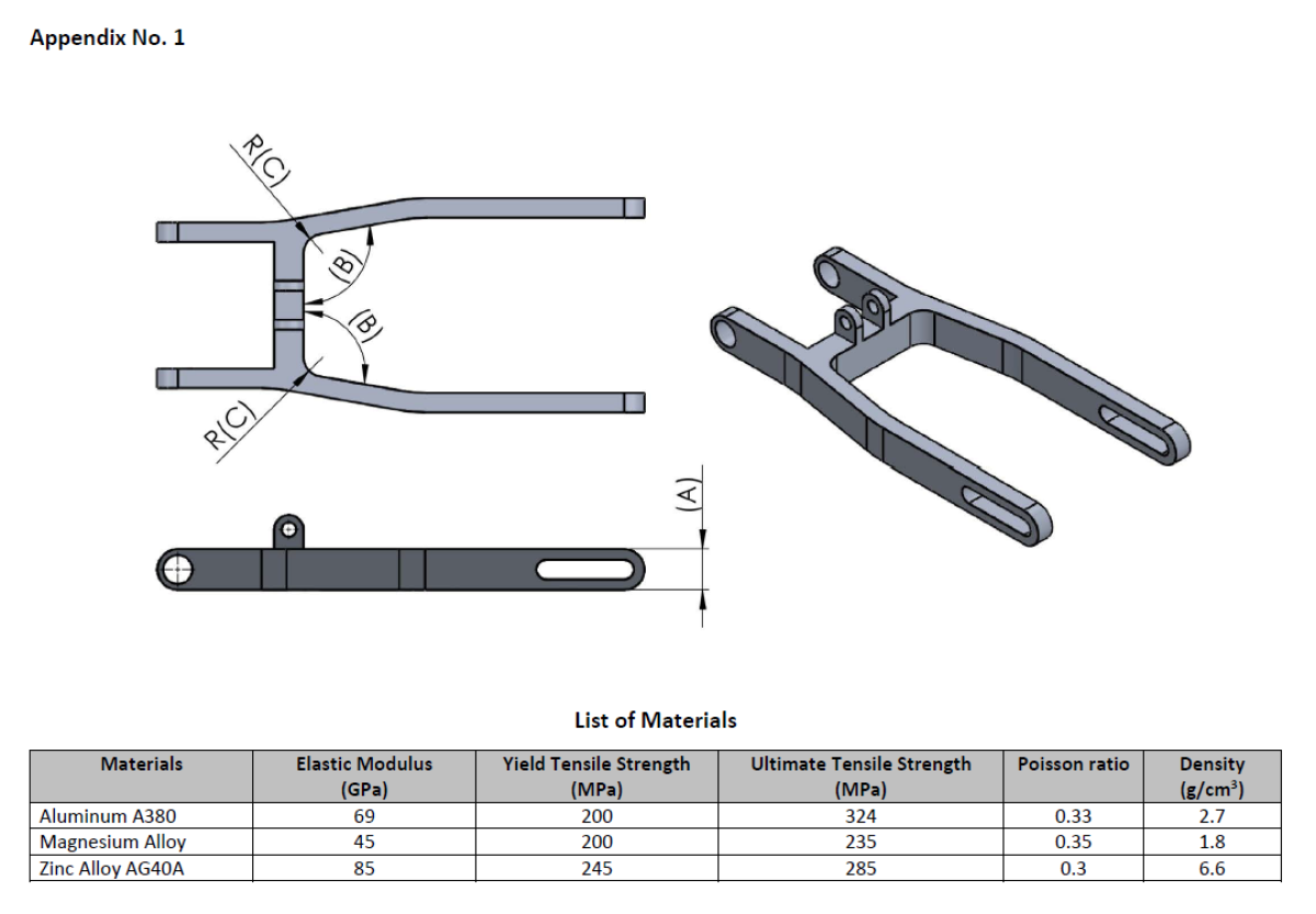
- Swing arm loads (N) for each load case, ready to apply at the chassis, shock absorber and wheel mounting points shown in the diagrams
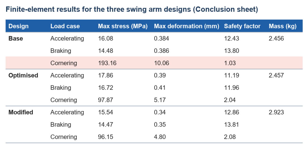
- A summary of maximum stress, deformation, safety factor and mass for the base, optimised and modified designs (results from a separate finite-element model, entered on the Conclusion sheet)
In the stored example (145 kg motorcycle, two riders, 65% on the rear axle) the static load on the swing arm is 1,881 N, the accelerating force 2,950 N at 10 m/s², the braking force 1,821 N (100 km/h to rest in 4.5 s) and the cornering loads 2,026 N on the inner arm and 868 N on the outer. Cornering governs: the base design's safety factor of 1.03 rises to about 2 in the optimised and modified designs.
Please note
- The "Number of riders" input is not used: each sheet assumes two riders of 75 kg.
- The braking force applies the whole bike's deceleration through the swing arm, and the cornering case uses the full weight rather than the rear-axle share; both are on the safe side.
- In the cornering case the vertical component uses the sine of the lean angle and the horizontal component the cosine. That suits an angle measured from the ground; if 40° is the lean from vertical, the two components are swapped.
- The stress and safety factor results are typed in from the author's finite-element study, so they do not update when the inputs change.
Author: Ishwar Gophane.
Calculation Preview
 (4/1)
Full download access to any calculation is available to users with a paid or awarded subscription (XLC Pro).
Subscriptions are free to contributors to the site, alternatively they can be purchased.
Click here for information on subscriptions.
Comments: 2
×

5 years ago
A nice debut calculation! I have awarded a three month XLC Pro subscription by way of thanks. An interesting calculation from first principles.
We have given your swing arm calculation a clearer title, a full description and larger preview pictures taken from your workbook, so that visitors can see what it does before downloading. The way it sets out the three load cases and then shows how the cornering safety factor improves from 1.03 to about 2 makes it a good teaching example.
While writing the description we noticed a few points, which we have mentioned on the page:
- The "Number of riders" input on the Inputs sheet is not used; each sheet assumes two riders of 75 kg.
- In the cornering case the vertical component uses SIN of the lean angle and the horizontal component COS. That is right if 40 degrees is measured from the ground, but if it is the lean from vertical the two are swapped.
- The braking and cornering cases use the whole bike's mass rather than the rear-axle share, which is on the safe side.
If you upload an updated version, we will review it and publish it as the next version.
ExcelCalcs Review Team