Flare Burning Combustion Calculation
Description
-
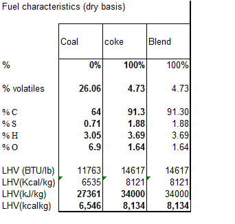
Input Fuel characteristics
-
Input kiln production data
-
Determine (goal seek) transport air flow rate : 5 kg/m3 for blower, 7 kg/m3 for pump
- vary the transport flowrate - Nm3/h
- note that blowers cannot take the higher material density rate
- Obtain optimum or target flow rates values (swirl & axial)
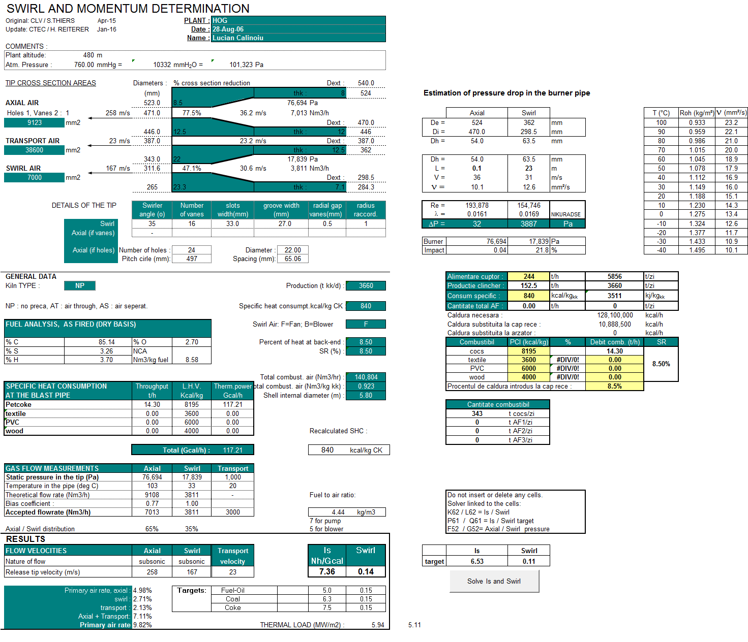
For a first calculation, start with static pressures of 40.000 Pa for axial, and 25.000 Pa for swirl - 10% primary air; 7% axial + transport (in case that no swirl is used). Use solver, changing the groove width, the axial holes diameters, the axial and the swirl static pressures. Add constraints on the axial pressure (35.000-60.000 Pa), and to the swirl pressure (>18.000 Pa if fan, 20.000-30.000 Pa if blower).
Note the optimum flow rates as well as cross section areas (mm2)
Ultimate target is Is = 1.8 and Sw = 0.15.
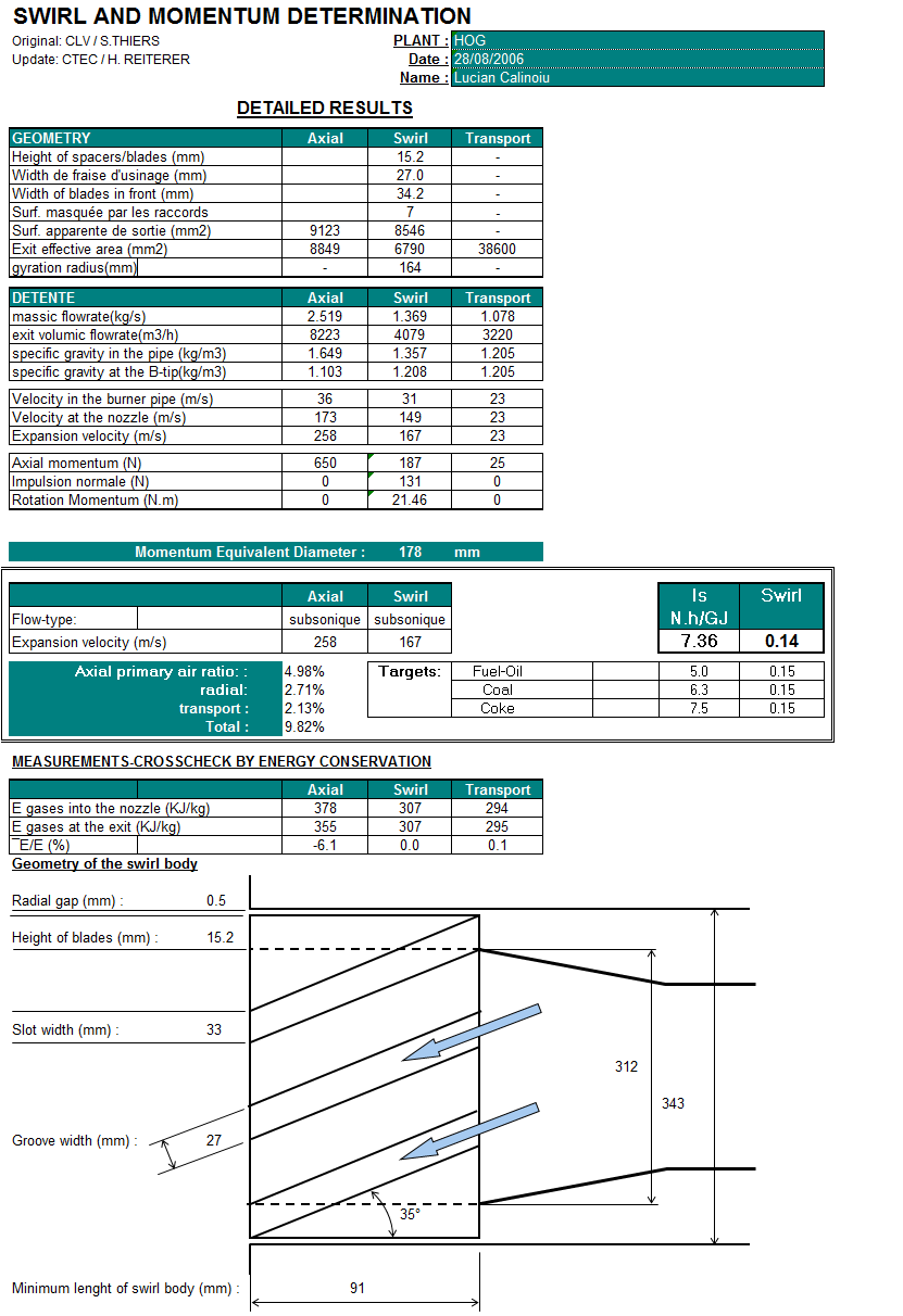
- Dimension the barrel:
What is the free diameter required in the centre? Depends on how many fuels the plant wants to burn simultaneously: waste, oil, etc…
In theory, min. of 200 mm (8 in.) is needed for the bluff body effect although 6 in. has been used.
a) Swirl:
b) Transport: Velocity in tip and barrel: 25 to 35 m/s
c) Axial: Velocity in barrel = 15 to 25 m/s (trade-off weight of burner pipe versus
- Once the barrel is complete, adjust the tip cross sectional areas Ultimate target is Is = 1.8 and Sw = 0.15, by adjusting the tip dimensions.
Change the tip cross sectional areas by adjusting the axial holes diameter and the width of groove for the swirl.
- Optimise static pressures at tip, tip cross sectional area and all other constraints. Obtain the best balance for:
Target of Is = 1.8 and Sw = 0.15,.
Optimum flow rates
- Confirm choice of fan or blower for swirl air based on static pressure in the tip - choice effects bias coefficient
- Determine range for blowers: maximum for (Is,Sw)=(1.8,0.15), and minimum for (0.9,0.05). Check that , doing this, we stay in the range
of 7 to 12% primary air.
Transport design: drawing instructions
Maximum angle of inlet = 12.5 degree with the burner axis
Enter from the top (better distribution)
Inlet rectangle: Internal width should be equal to internal
diameter of outer pipe of the fuel annulus. The velocity
should never decrease from the fuel intoduction into the line
to the burner tip. (Settlement)
Calculation Reference
Flare Burning Combustion
Thermodynamics
Gas Flaring
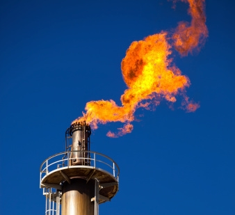
Swirl movement and momentum calculations are important considerations in the design of an air burner, which is a combustion system used to dispose of various types of waste materials by burning them in a controlled environment. The swirl movement in an air burner is created by tangential injection of air into the combustion chamber, which creates a vortex or swirling motion of the air and waste materials.
The swirl movement and momentum calculations are used to determine the optimal design of the air burner, including the diameter and height of the combustion chamber, the injection angle and velocity of the air, and the residence time of the waste materials in the combustion zone. These calculations are based on the principles of fluid mechanics and thermodynamics, and take into account factors such as the temperature, pressure, and velocity of the air and waste materials.
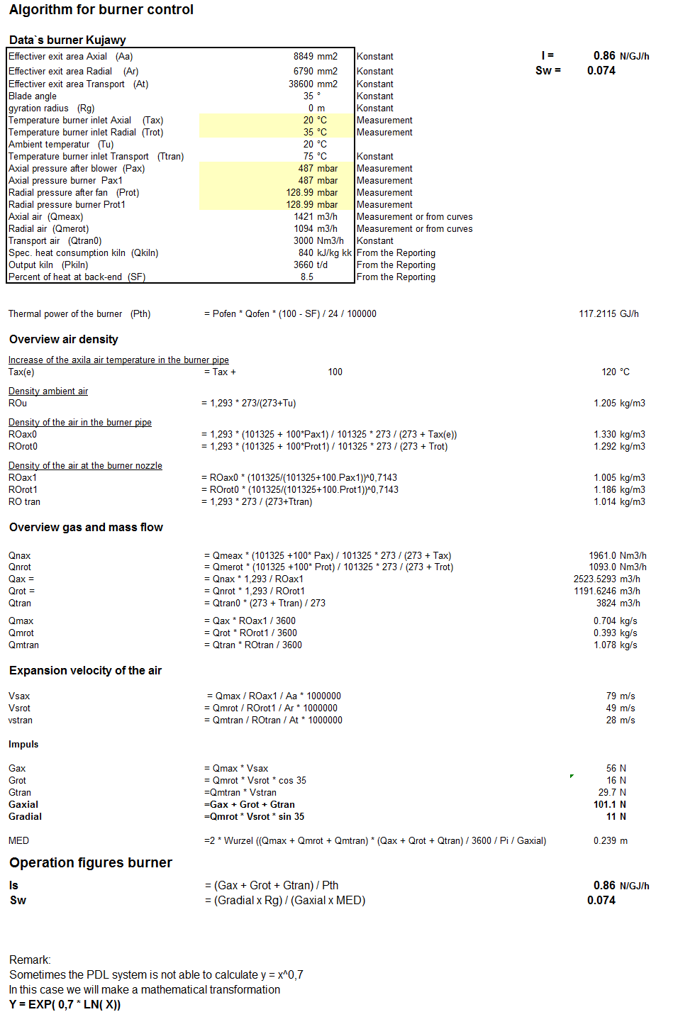
The swirl movement calculation involves determining the swirl velocity of the air in the combustion chamber, which is the tangential velocity of the air as it enters the chamber. This can be calculated using the formula V_s = Q_t / (πr^2), where V_s is the swirl velocity, Q_t is the total flow rate of the air, and r is the radius of the combustion chamber.
The momentum calculation involves determining the momentum of the air and waste materials in the combustion chamber, which is a measure of the force that drives the combustion process. This can be calculated using the formula P = ρAV, where P is the momentum, ρ is the density of the air and waste materials, A is the cross-sectional area of the combustion chamber, and V is the velocity of the air and waste materials.
Optimizing the swirl movement and momentum in an air burner is critical for efficient and effective combustion of the waste materials. The calculations can be used to adjust the design parameters of the air burner, such as the injection angle and velocity, to achieve the desired swirl movement and momentum.
Calculation Preview
Full download access to any calculation is available to users with a paid or awarded subscription (XLC Pro).
Subscriptions are free to contributors to the site, alternatively they can be purchased.
Click here for information on subscriptions.