Buoyancy control analysis
Description
CALCULATION FOR SET ON WEIGHT
Pipe size
Outside diameter, OD
Wall thickness, t
Weight of pipe, WP
Density of water, r
Buoyant force (Pipe), BP
Weight of set on weight, WC
Volume of set on weight, VC
Bouyant force (Set on weight), BC
A) FOR GOOD SOIL IN HIGH WATER TABLE
Soil bulk density, BD 1.5 T/m3
Minimum depth of cover
Bulk density
Bulking factor
Submerge bulk density
Submerge and disturbed weight of over burden soil, WS
Buoyancy Control Formula:
where L is the center to center weight spacing.
Center to center weight spacing, L
B) FOR PARTIALLY GOOD SOIL IN HIGH WATER TABLE
Soil bulk density
At depth less than 2.0 m
Vane test result 0.00025 N/mm²
Minimum depth of cover
Bulk density
Bulking factor
Submerge bulk density
Submerge and disturbed weight of over burden soil, WS
Center to center weight spacing, L
C) FOR POOR SOIL IN HIGH WATER TABLE
Soil bulk density BD 1.35 T/m3 at all depth, remolded vane test result 0.00025 N/mm²
Minimum depth of cover
Bulk density
Bulking factor
Submerge bulk density
Submerge and disturbed weight of over burden soil, WS
Center to center weight spacing, L
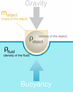
Buoyancy control analysis is a crucial aspect of designing and operating floating structures, underwater vehicles, and various marine systems. It involves evaluating the forces acting on the submerged or floating object, ensuring that it maintains the desired depth, position, and stability in the water. The key parameters to consider in a buoyancy control analysis include buoyancy force, weight, and center of gravity.
Here are the essential steps for conducting a buoyancy control analysis:
-
Determine the object's volume: Calculate the volume of the submerged or floating object. This volume is crucial in determining the buoyancy force acting on the object.
-
Calculate the buoyancy force: The buoyancy force (FB) acting on the object can be calculated using Archimedes' principle:
FB = ρ_water * V * g
where:
- ρ_water = density of water (approximately 1000 kg/m³ for freshwater and 1025 kg/m³ for seawater)
- V = volume of the submerged or floating object (m³)
- g = acceleration due to gravity (approximately 9.81 m/s²)
- Calculate the weight of the object: Determine the weight (W) of the object, which can be calculated as:
W = m * g
where:
- m = mass of the object (kg)
- g = acceleration due to gravity (approximately 9.81 m/s²)
-
Compare the buoyancy force and weight: To maintain a stable depth or position in the water, the buoyancy force (FB) must equal the object's weight (W). If FB > W, the object will float, and if FB W, the object will sink. Adjustments to the object's volume, mass, or buoyancy control systems (e.g., ballast tanks or buoyancy compensators) can be made to achieve the desired equilibrium.
-
Determine the center of gravity and center of buoyancy: The center of gravity (CG) is the point where the object's weight is concentrated, while the center of buoyancy (CB) is the point where the buoyancy force is concentrated. For a stable configuration, the CB should be vertically aligned with the CG. If the CB is above the CG, the object will be in an unstable configuration and may capsize.
-
Stability analysis: Analyze the object's stability by calculating the metacentric height (GM) and righting moment. A positive GM indicates a stable configuration, while a negative GM indicates an unstable configuration. Adjustments to the object's shape, mass distribution, or buoyancy control systems may be required to ensure stability.
Buoyancy control analysis is vital for the safe and efficient operation of various marine systems, such as submarines, remotely operated vehicles (ROVs), autonomous underwater vehicles (AUVs), and floating structures like ships and offshore platforms. The analysis ensures that these systems maintain their desired depth, position, and stability in the water, minimizing the risk of accidents and optimizing performance.
Calculation Preview
Full download access to any calculation is available to users with a paid or awarded subscription (XLC Pro).
Subscriptions are free to contributors to the site, alternatively they can be purchased.
Click here for information on subscriptions.