
Rigid Body Transform
 (0/0)
(0/0)
Description
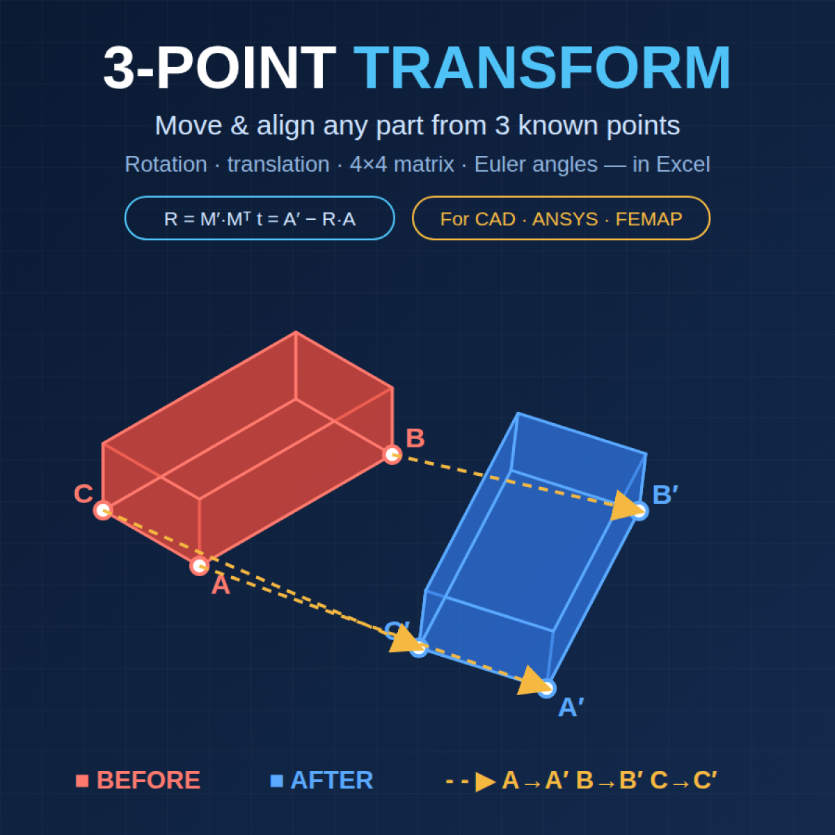
3-Point Transform is a macro-free Microsoft Excel workbook that solves a problem every CAD and FEA user runs into: a part that is the right shape but in the wrong place. Geometry imported on the wrong coordinate system, a component that needs to mate to an assembly, a mesh that has to be aligned to a test fixture or a global frame — all of them come down to the same question: what rotation and translation moves this body from where it is to where it belongs? Enter three known points on the part (A, B, C) and the same three points at their intended location (A′, B′, C′), and the workbook returns the complete rigid-body transformation that carries one onto the other. No add-ins, no VBA, nothing to install; every result is a live formula you can trace.
The math is done the way a structural analyst would do it by hand, just faster. The three source points define an orthonormal local frame; the three target points define another; the rotation matrix is the product of one frame with the transpose of the other, and the translation is whatever is left after rotating point A. Because three non-collinear points fully constrain a rigid body, the answer is exact and unique — no iteration, no least-squares, no matrix inversion. Results are delivered in every form a downstream package might ask for: the 3×3 rotation matrix and translation vector, the 4×4 homogeneous transform ready to paste into a CAD or FEA tool, the equivalent angle-and-axis rotation, and ZYX Euler angles (yaw, pitch, roll) with the application order spelled out.
Built-in checks keep you honest. A rigidity table compares the AB, AC and BC distances between the source and target triads so you know immediately if you picked the wrong points, mixed units, or are trying to force geometry that is not actually the same shape. A residual block applies the computed transform back to the source points and reports how far they land from the targets — exactly zero for a true rigid move, and a quantified warning when it is not. The determinant of the rotation matrix is displayed to confirm a proper right-handed rotation. A Plot sheet shows the before-and-after triangles in isometric, top, front and side views, with the transformed source overlaid on the target so you can see the alignment rather than trust it.
A How To sheet documents the full method and then walks through applying the result in practice: ANSYS Mechanical Part Transform by coordinate system or by rotation and translation, SpaceClaim and Discovery Move and Align, DesignModeler Body Operation Move by Vertices, Mechanical APDL coordinate systems from keypoints with TRANSFER and the KTRAN/LTRAN/ATRAN/VTRAN family, and FEMAP Model → Coord Sys with Modify → Align, Rotate By and Move By — including the rotation-order traps in each package and how to verify a point afterward. The recommended coordinate-system-to-coordinate-system route is explained so you can let the software do the matrix work when it can, and fall back to the numbers from this sheet when it cannot.
Ships with a worked example using an exact rotation and translation so every residual reads zero out of the box. Replace six rows of coordinates with your own and the workbook does the rest.
Calculation Preview
(0/0)
Full download access to any calculation is available to users with a paid or awarded subscription (XLC Pro).
Subscriptions are free to contributors to the site, alternatively they can be purchased.
Click here for information on subscriptions.