ThermalTransient1D.xls

Description
A spreadsheet to calculate transient temperatures through a wall in either XY, cylindrical or spherical coordinate systems assuming one dimenional heat flow through the thickness and forced convection on both inner and outer surfaces. The spreadsheet uses the unconditionally stable Crank Nicolson finite difference method to calculate temperatures over a fixed time interval given an initial uniform temperature distribution.
One Dimensional Heat Diffusion in XY, Cylindrical or Spherical coordinate systems
α.∂T/∂t = ∂2T/∂x2 + p/x. ∂T/∂x + 1/k.g(x,t) (1)
where p=0 for XY geometry, 1 for cylindrical system and 2 for a spherical coordinate system, and
α = ρ.Cp/k (density x specific heat/conductvity). g(x,t) is a heat source assumed to be constant.
For simplicity all properties are assumed to be constant.
This spreadsheet solves the one dimensional transient heat flow equation (1) across a single material domain for different coordinate systems. Boundary conditions are provided by forced convection from the boundary surfaces. In the case of cylindrical or spherical coordinate systems, a solid rod or sphere can be represented by setting the inner dimension to zero. In those cases adiabatic (zero heat flow) occurs at the centre of the rod or sphere. The initial condition is assumed to be a uniform temperature.
The method used is the unconditionally stable Crank-Nicolson finite difference scheme coupled with an implicit backward difference scheme at the boundary nodes to ensure stability.
As with all finite difference methods, the accuracy of the results is dependent upon the time step and discretisation of the region. The format of the spreadsheet allows the region to be discretised by up to 17 equally spaced nodes which should be sufficient for most purposes. In addition the total time interval is discretised into 500 equal time steps. For severe transients a smaller total time should be chosed to ensure a smaller time step and greater accuracy.
Although the boundary condition is specified as forced convection where -k.∂T/∂ṉ = h.(T-Ta) at the surface, fixed temperatures can be imposed by setting the value of the heat reansfer coefficient, h, to be high such that the surface temperature T→Ta where Ta is the required fixed temperature. In addition a fixed heat flux can be set by setting h to be very small but so that the product of h and Ta equals the fixed heat flux. Adiabatic conditions (zero heat flow at insulated surfaces) are imposed by setting h to zero.
The user can select units of either mm or metres for convenience only. Imperial units are not provided due to the complexity of conversion between the different material properties and a general inconsistent use of feet and inches that baffles everyone.
A steady state solution to the heat flow can be obtained by setting Specific heat or Density to zero. The solution through time will of course be constant.
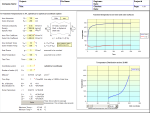
Following input of the required fields the user should click the 'Solve' button to calculate temperatures throughout the transient at all nodal positions. This should take a few seconds to complete.
Results are shown both graphically, and in full within the table below the input fields. Graphs show the calculated temperatures at the inner and outer surfaces throughout the transient, together with calculated temperatures across the section width at a time selected by the user. This can be achieved by selecting a time from the drop down box or by moving the scroll bar across. The latter gives an animated effect to the temperature distribution through the section as they vary throughout the transient.
Verification
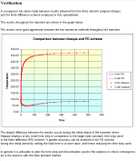
A comparison has been made between results obtained from the finite element program Abaqus and the finite difference scheme employed in this spreadsheet.
The results throughout the transient are shown in the graph.
The results show good agreement between the two numerical methods throughout the transient.
The largest difference between the results occurs during the initial phase of the transient where Abaqus employs a very small time step in comparison to the larger (and constant) time step used in the finite difference (FD) scheme. A greater accuracy can be achieved in the FD scheme during this initial period by setting the total time to a lower value, and hence reducing the time step used.
In general it is advisable to alter the time step and discretisation used in the analysis to check convergence, as is the practice with the finite element method.
Calculation Reference
Thermal Transient Analysis
Thermal Analysis
Rapid Heating and Cooling Analysis
Calculation Preview
Full download access to any calculation is available to users with a paid or awarded subscription (XLC Pro).
Subscriptions are free to contributors to the site, alternatively they can be purchased.
Click here for information on subscriptions.


