
Bolt Joint Quick – Threaded-Fastener Joint Analysis to NASA-STD-5020B
 (0/0)
(0/0)
Description
Bolt Joint Quick – Threaded-Fastener Joint Analysis to NASA-STD-5020B
Bolt Joint Quick is a macro-free Excel workbook for the complete strength, separation, and fatigue assessment of a preloaded bolted joint, built for aerospace work and organized around NASA-STD-5020B, Requirements for Threaded Fastening Systems in Spaceflight Hardware. The whole analysis lives on one Analysis page that reads top to bottom: project data, units, fastener, joint stack, torque and preload, loads, and factors, with every result, margin of safety, and chart on the same sheet. There is nothing to install and nothing to enable; every equation is a visible worksheet formula that can be traced, checked and signed.
The fastener is chosen from UNC, UNF and ISO metric threads (with UN or UNJ minor-diameter tension areas where MMPDS requires them), with two separate, switchable material libraries that are never mixed: MMPDS-01 aerospace fasteners and member allowables (A- or B-basis, with tabulated Tables 8.1.5(a), (b1) and (b2) shown alongside the computed values as a cross-check), or a commercial database of SAE J429 and ISO 898-1 grades with a 133-row bolt table of stress areas, proof loads and recommended dry and lubricated torques. The clamped stack takes up to four plate or washer layers of different materials, for through-bolts with a nut, threaded inserts or blind tapped holes, and a live indicator shows which layers are in use. Joint stiffness is calculated with 30-degree frustum cones through each layer (Shrigley Eq. 8-19) or the NASA closed form. The load-introduction factor n is entered directly or derived from the stack by 5020B Eq. 37 (loading planes at mid-thickness of the outer plates), and the product nφ can be overridden with a finite element value.
Preload follows 5020B Eqs. 1 to 5: torque nominal and tolerance, a torque range, or a target percentage of proof; nut factor from an input, a lubrication table or thread and bearing friction (Motosh long form); prevailing torque and relaxation; and the thermal preload change from installation to hot and cold service temperatures, including both differential expansion and the change of bolt and member modulus with temperature. Minimum preload is assigned by checking as the standard requires: full scatter Γ (Eq. 4) for separation-critical joints and for fatigue, Γ/√nf (Eq. 5) for slip and for separation of joints that are not separation-critical. The separation factor of safety follows 5020B Figure 1, based on the hazard the separation would cause.
Margins of safety are computed for ultimate and yield tension with the 5020B separation-versus-rupture logic (Eqs. 6, 7, 15 to 18), separation (Eq. 19), shear, tension-shear-bending interaction (Eqs. 20 to 23, elastic or plastic bending, with the legacy Rt² + Rs³ curve and custom exponents also available), von Mises, external, internal and combined thread stripping on FED-STD-H28 minimum-material areas from the 2A/2B or 6g/6H tolerances, nut or insert rated strength, head and nut-face bearing, hole bearing to MMPDS-01 with e/D interpolation and an optional wet-pin factor, installation stress under combined tension and torsion, and friction slip to 5020B Eq. 86. Switches let yield checks be reported for information where yielding is not detrimental, and the same for the installation check. Fatigue is evaluated against Goodman, Gerber, ASME-elliptic and Soderberg with the load line starting from preload, with an S-N life estimate and the NASA-STD-5001B service life factor of 4. A NASA-5020B tab lists the standard's requirements against the joint and evaluates the seven Appendix C similarity conditions for low likelihood of fatigue failure, with Table 7 reproduced. The governing margin and every input check are summarised in a status bar at the top of the page.
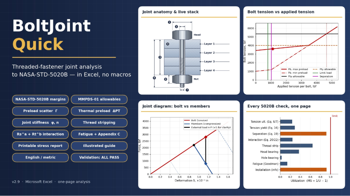
Charts include the bolt tension versus applied tension diagram with maximum and minimum preload, Pty and Ptu allowable, limit and ultimate loads, separation loads and load to rupture; the joint diagram across the preload band; the fatigue diagram; the interaction curve; and a margin summary. A print-ready Report tab produces a NASA-style stress report for the critical fastener with each equation, the numbers substituted into it and the 5020B equation or requirement it comes from, plus a compliance matrix and sign-off block. An illustrated Guide tab explains the joint anatomy, torque, preload, stiffness, loads, margin logic and fatigue with live values from your joint, and a Validation tab checks the workbook against published values and closed-form identities on every recalculation. A separate Word user guide and theory manual gives the source of every equation and three worked examples. English and metric units are supported throughout.
Author: Alan Moss
Calculation Preview
(0/0)
Full download access to any calculation is available to users with a paid or awarded subscription (XLC Pro).
Subscriptions are free to contributors to the site, alternatively they can be purchased.
Click here for information on subscriptions.