Detailed Bolted Joint Calculations
Description
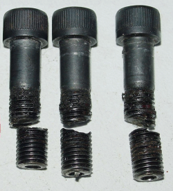
An elastic bolted joint is a mechanical connection between two or more structural components using bolts, providing clamping force to hold the parts together. The mechanics of an elastic bolted joint involve the balance between the applied external load and the clamping force generated by the bolts. Here's a summary of the mechanics of an elastic bolted joint and how to prevent slip:
-
Clamping Force: When a bolt is tightened, it stretches and generates a clamping force between the connected components. This force is also known as preload or the initial bolt tension. The clamping force is a result of the bolt's elasticity, and it is essential for maintaining the integrity of the joint.
-
Applied Load: When an external load is applied to the joint, it generates forces and moments that act on the connected components. These forces can be axial, shear, or a combination of both, depending on the specific application.
-
Load Distribution: The applied load is distributed between the clamping force and the friction between the joint interfaces. In an elastic bolted joint, the clamping force should be high enough to prevent the applied load from overcoming the friction force and causing slip.
-
Friction Force: The friction force between the connected components is a function of the clamping force and the friction coefficient. It acts as a resistance against the applied load and prevents the joint from slipping.
To prevent slip in an elastic bolted joint, consider the following factors:
-
Bolt Preload: Ensure that the preload generated by tightening the bolts is high enough to maintain the clamping force required to resist the applied loads. This can be achieved by selecting the appropriate bolt size, material, and tightening torque.
-
Friction Coefficient: Choose materials with suitable friction coefficients for the joint interfaces. Rougher surfaces or materials with higher friction coefficients can provide better slip resistance. Additionally, consider using friction-enhancing coatings or treatments, such as zinc phosphate or manganese phosphate.
-
Joint Design: Optimize the joint design to distribute the applied load evenly across all bolts. This can include selecting the appropriate bolt pattern, spacing, and edge distances.
-
Bolt Quantity: Use an adequate number of bolts to distribute the applied load and maintain the required clamping force. More bolts can help reduce the individual bolt load and increase the overall slip resistance of the joint.
-
Tightening Technique: Employ a proper bolt tightening technique, such as torque control, angle control, or bolt elongation measurement, to ensure consistent and accurate preload across all bolts.
-
Maintenance and Inspection: Regularly inspect and maintain the bolted joint to ensure its continued performance. This may involve checking for loose bolts, corrosion, or other signs of wear and damage.
In summary, the mechanics of an elastic bolted joint involve the balance between the clamping force generated by the bolts and the applied external load. To prevent slip, it is essential to ensure adequate bolt preload, select appropriate materials and friction coefficients, optimize joint design, use an adequate number of bolts, employ proper tightening techniques, and perform regular maintenance and inspection
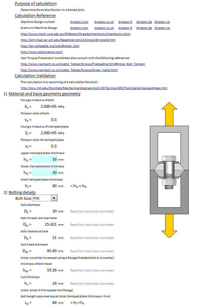
Purpose of calculation:Determine force distribution in a bolted joint.
Calculation Reference
Machine Design Juvinall
Scahum's Machine Design
http://www.mech.uwa.edu.au/DANotes/threads/mechanics/mechanics.html
http://em-ntserver.unl.edu/Negahban/em223/note16/note16.htm
http://en.wikipedia.org/wiki/Bolted_joint
http://www.boltscience.com/
Use 'Torque Pretension' worksheet also consult with the following references
https://roymech.org/Useful_Tables/Screws/Preloading.html#Initial_Bolt_Tension
https://roymech.org/Useful_Tables/Screws/Screw_loads.html
Calculation Validation
http://ocw.mit.edu/OcwWeb/Mechanical-Engineering/2-007Spring-2005/Tools/detail/spreadsheet.htm
1) Material and basic geometry geometry
Young's modulus of bolt
Poisson ratio of bolt
Young's modulus of clamped plate
Poisson ratio of clamped plate
upper clamped plate thickness
lower clamped plate thickness
total clamped plate thickness
2) Bolting details
bolt diameter
bolt thread root diameter
bolt clearance hole
bolt head diameter
(note: could be increased using a flanged headed bolt or a washer)
thickness of bolt head
nut thickness
(note: enter 0 if threaded into flange)
bolt length assumed equal total clamped plate thickness + hnut
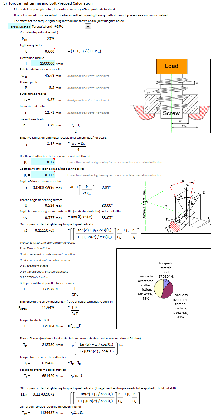
3) Torque Tightening and Bolt PreLoad Calculation
Method of torque tightening determines accuracy of bolt preload obtained.
It is not unusual to increase bolt size because the torque tightening method cannot guarentee a minimum preload.
The effects of the torque tightening method are shown on the joint diagram below.
Variation in preload (+ and -)
Tightening Torque (to yield bolt see Eqn. 37)
Bolt head dimension across flats
Thread pitch
outer thread radius
inner thread radius
mean thread radius
Effective radius of rubbing surface against which head/nut bears
Coefficient of friction between screw and nut thread
Coefficient of friction at head/nut bearing collar
Thread Lead (equals thread pitch for single thread screws)
Angle of thread at mean radius
Thread angle at bearing surface
Angle between tangent to tooth profile (on the loaded side) and a radial line
Thread Constant
Bolt preload (load parallel to screw axis)
Efficiency of the screw mechanism (ratio of useful work out to work in)
Torque to stretch Bolt
Thread Torque (torsional load in the bolt to stretch the bolt and overcome thread friction)
Torque to overcome thread friction
Torque to overcome collar friction
Joint pretension constants to compare with other threads
Typical K factors for comparison purposes
Steel Thread Condition
0.30 as received, stainless on mild or alloy
0.20 as received, mild or alloy on same
0.16 cadmium plated
0.14 molybdenum-disulphide grease
0.12 PTFE lubrication
Off Torque - torque required to loosen the nut (if negative then torque needs to be applied to hold nut still)
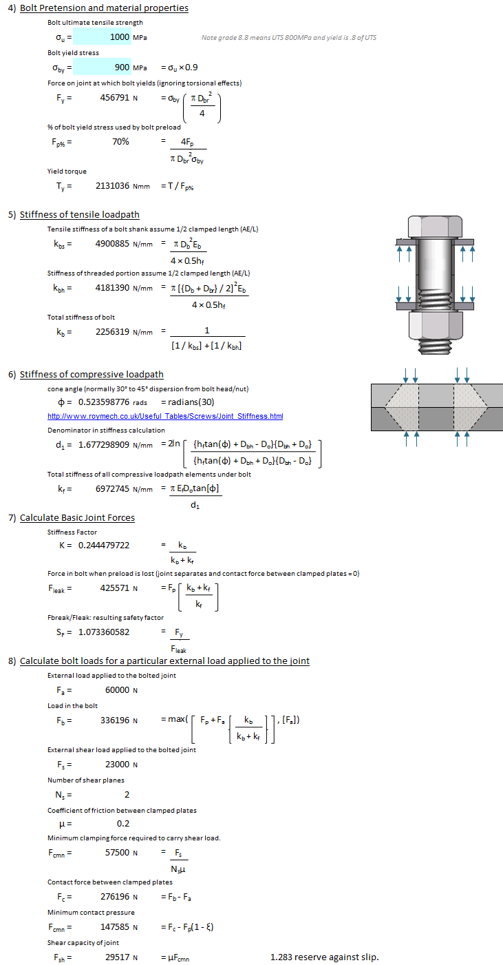
Bolt Pretension and material properties
Bolt ultimate tensile strength
Bolt yield stress
Force on joint at which bolt yields (ignoring torsional effects)
% of bolt yield stress used by bolt preload
4) Stiffness of tensile loadpath
Tensile stiffness of a bolt shaft
Shear stiffness of a bolt head
Shear stiffness of a nut
Total stiffness of bolt
5) Stiffness of compressive loadpath
cone angle (normally 45° dispersion from bolt head/nut)
Compressive stiffness of clamped plates (in series)
Shear stiffness of clamped plates
Total stiffness of all compressive loadpath elements under bolt
6) Calculate Basic Joint Forces
Force in bolt when preload is lost (joint separates and contact force between clamped plates = 0)
Fbreak/Fleak: resulting safety factor
7) Calculate bolt loads for a particular external load applied to the joint
External load applied to the bolted joint
Load in the bolt
External shear load applied to the bolted joint
Contact force between clamped plates
Coefficient of friction between clamped plates
Shear capacity of joint
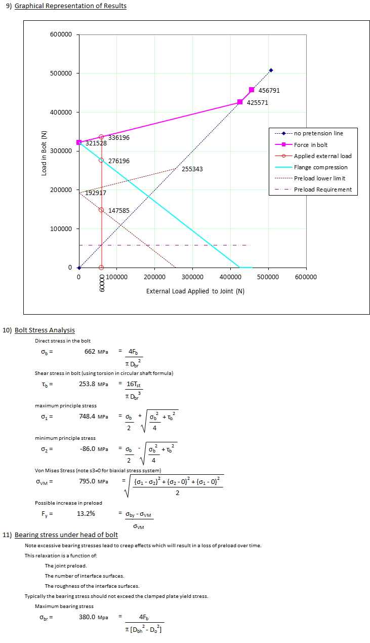
8) Graphical Representation of Results
9) Bolt Stress Analysis
Direct stress in the bolt
Shear stress in bolt (using torsion in circular shaft formula)
maximum principle stress
minimum principle stress
Von Mises Stress (note s3=0 for biaxial stress system)
Possible increase in preload
10) Bearing stress under head of bolt
Note excessive bearing stresses lead to creep effects which will result in a loss of preload over time.
This relaxation is a function of:
Typically the bearing stress should not exceed the clamped plate yield stress.
Maximum bearing Stress
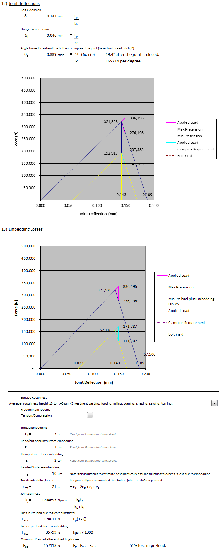
11) Joint deflections and nut rotation.
Bolt extension
Flange compression
Angle turned to extend the bolt
12) Losses at Clamped Surfaces
Paint compression factor
Maximum paint thickness (specification)
Number of painted surfaces
Preload after paint compression
Maximum paint thickness (specification)
Preload after paint compression
A simpler version of this calculation is available here.
Calculation Reference
Handbook of bolts and bolted joints
American Machinists' Handbook and Dictionary of Shop Terms
Basic Principles for Construction, Cengage Learning
Machinery's Handbook
https://youtube.com/playlist?list=PLJIW9uae3iwbzodRCWhCHXtJ23CHMm1M4
Calculation Preview
Full download access to any calculation is available to users with a paid or awarded subscription (XLC Pro).
Subscriptions are free to contributors to the site, alternatively they can be purchased.
Click here for information on subscriptions.