
Self-Tapping Screw Connection Check (ASD) - AAMA TIR-A9-14
 (0/0)
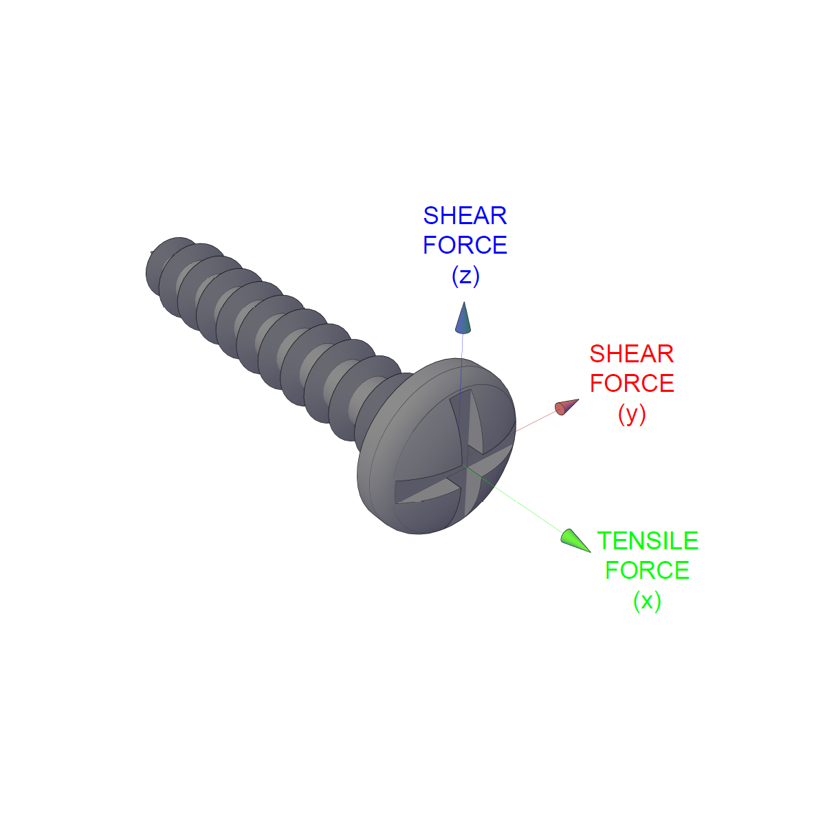
Description
Self-Tapping Screw Connection Check (ASD) to AAMA TIR-A9-14
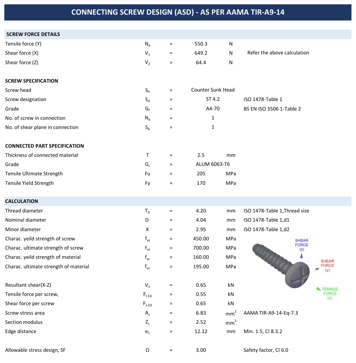
An allowable stress design check of a stainless steel self-tapping screw in an aluminium connection, following AAMA TIR-A9-14 (Design Guide for Metal Cladding Fasteners). From the applied tension and two shear components it calculates the allowable tension and shear of the screw on its thread root area, the allowable bearing on the screw and the connected part, and the combined tension and shear interaction, and reports the governing utilisation.
Inputs
- Tension Na and shear forces V1, V2 on the screw (N)
- Screw head type, designation (ISO 1478), grade (ISO 3506-1), number of screws and shear planes
- Thickness and grade of the connected part, and the strengths of screw and connected material
- Allowable stress safety factor Ω (3 in the example)
Outputs
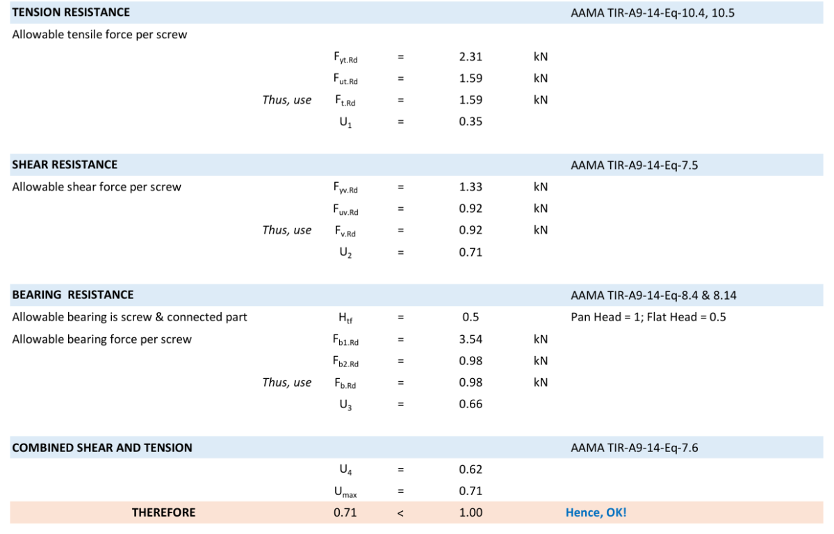
- Allowable tension Ft.Rd, the lesser of the yield and ultimate limits
- Allowable shear Fv.Rd
- Allowable bearing on the screw and on the connected part
- Combined tension and shear interaction (U1² + U2²)
- The maximum utilisation and an OK / not OK verdict
The example is an ST 4.2 grade A4-70 countersunk screw in 2.5 mm 6063-T6 aluminium; shear governs with a utilisation of 0.71. SI units.
Checked and corrected
Every result was recomputed independently. ExcelCalcs made four corrections to the uploaded file (17 November 2026, version 1.1):
- Ultimate tension capacity now divides by the safety factor, as the written formula says (As · fus ÷ Ω). The original multiplied by Ω and divided by 10,000. Fut.Rd is now 1.59 kN, not 1.44 kN.
- The head factor now follows the screw head chosen: 1 for a pan head, 0.5 otherwise. The example's countersunk screw was using the pan-head value, so the bearing utilisation rises from 0.33 to 0.66.
- The final comparison sign now compares the utilisation with 1. It read “0.71 > 1” whatever the result.
- The written formula for Fuv.Rd no longer shows a factor of 0.75 that the calculation does not use.
Please note
- The bearing capacity is taken as e1 · T · fu · Htf ÷ Ω, with the edge distance fixed at 3 × the screw diameter. Check it against Eq. 8.4 and 8.14 of the TIR for your edge distance.
- Screw pull-out and pull-over are not checked; in thin aluminium in tension they can govern.
Calculation Preview
 (0/0)
Full download access to any calculation is available to users with a paid or awarded subscription (XLC Pro).
Subscriptions are free to contributors to the site, alternatively they can be purchased.
Click here for information on subscriptions.
Comments: 2
×

3 days ago
Thank you for taking the trouble to upload your calculation, Ronald, and apologies for taking so long to review it. The written formula beside every result makes it easy to follow and to check. On this occasion we have decided not to publish the calculation as cell E42 multiplies by the safety factor instead of dividing.
**What needs to change**
- E42 multiplies by the safety factor; it should divide: As × fus ÷ Ω ÷ 1,000.
- The comparison in C62 should test the utilisation in E61.
- Make the head factor in E53 follow the head type chosen in E9.
- Make the written formula at D48 match the cell formula.
- Check the bearing equation against the TIR and add the actual edge distance as an input.
- Add pull-out and pull-over checks, or say plainly that they are done elsewhere.
- Choose the screw size, grade and alloy from drop-down lists that fill in the properties.
- Say how you know it is right, for example by reproducing a worked example from the TIR. With the corrections, that would bring it close to the 12-month award.
We offer guidance for authors on The Good Calculation Guide: [https://www.excelcalcs.com/calcs/good-calc-guide](https://www.excelcalcs.com/calcs/good-calc-guide). If you upload a corrected version we'll be glad to review it again: a corrected calculation earns a 3-month XLC Pro subscription, and one that follows the guide in full earns 12 months. We hope that this does not discourage you and thanks for your interest in the site.
**What needs to change**
- E42 multiplies by the safety factor; it should divide: As × fus ÷ Ω ÷ 1,000.
- The comparison in C62 should test the utilisation in E61.
- Make the head factor in E53 follow the head type chosen in E9.
- Make the written formula at D48 match the cell formula.
- Check the bearing equation against the TIR and add the actual edge distance as an input.
- Add pull-out and pull-over checks, or say plainly that they are done elsewhere.
- Choose the screw size, grade and alloy from drop-down lists that fill in the properties.
- Say how you know it is right, for example by reproducing a worked example from the TIR. With the corrections, that would bring it close to the 12-month award.
We offer guidance for authors on The Good Calculation Guide: [https://www.excelcalcs.com/calcs/good-calc-guide](https://www.excelcalcs.com/calcs/good-calc-guide). If you upload a corrected version we'll be glad to review it again: a corrected calculation earns a 3-month XLC Pro subscription, and one that follows the guide in full earns 12 months. We hope that this does not discourage you and thanks for your interest in the site.
**What we corrected**
- E42 now divides by the safety factor, as your written formula says: Fut.Rd = As × fus ÷ Ω = 1.59 kN (it was 1.44 kN).
- E53, the head factor, now follows the head type in E9: 1 for a pan head, 0.5 otherwise. For your countersunk example the bearing utilisation becomes 0.66.
- C62 now compares the utilisation in E61 with 1, so the result reads "0.71 he Good Calculation Guide: [https://www.excelcalcs.com/calcs/good-calc-guide](https://www.excelcalcs.com/calcs/good-calc-guide).