Beam Capacity Checking

Description
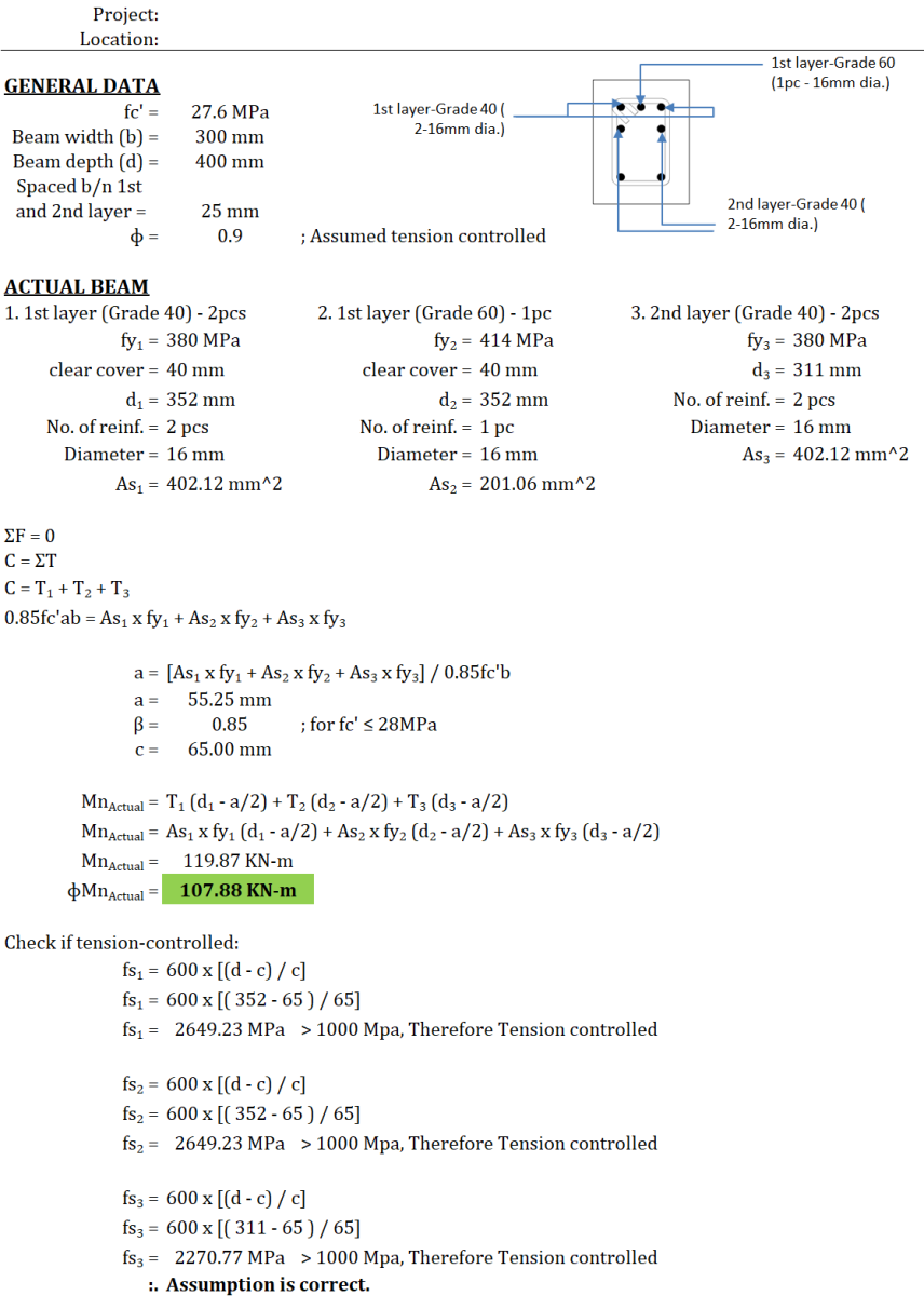
Core Engineering Principle: Concrete Beam Moment Resistance
This calculation follows the principle that in a reinforced concrete beam, concrete resists compression while steel reinforcement resists tension, and the beam's strength depends on achieving equilibrium between these forces.
1. Force Equilibrium Concept
- When a concrete beam bends, the top portion goes into compression (concrete handles this well)
- The bottom portion goes into tension (concrete is weak here, so steel rebar is needed)
- For the beam to be stable: Compression Force = Total Tension Force
- This is expressed as: C = T₁ + T₂ + T₃ (sum of all tension forces)
2. Stress Block Method
- The calculation uses the "equivalent rectangular stress block" - a simplified way to represent the actual curved stress distribution in concrete
- The concrete compression is calculated as: C = 0.85 × f'c × a × b
- Where 'a' is the depth of the equivalent compression block
3. Multi-Layer Reinforcement Analysis This beam has steel bars at different depths (layers), which affects capacity:
- Different grades of steel (Grade 40 vs Grade 60) have different yield strengths
- Different positions (closer to or farther from the compression zone) contribute differently to moment resistance
- Each layer contributes: T = As × fy (steel area × yield strength)
4. Moment Arm Principle
- The moment capacity depends not just on the forces, but on their lever arms (distances)
- Each tension force creates moment: M = T × (distance from compression center)
- Total moment = sum of all individual contributions
5. Tension-Controlled Verification
- The calculation checks that the steel yields before concrete crushes
- This ensures ductile failure (steel stretches and gives warning) rather than brittle concrete failure
- The fs > 1000 MPa check confirms the beam will fail safely
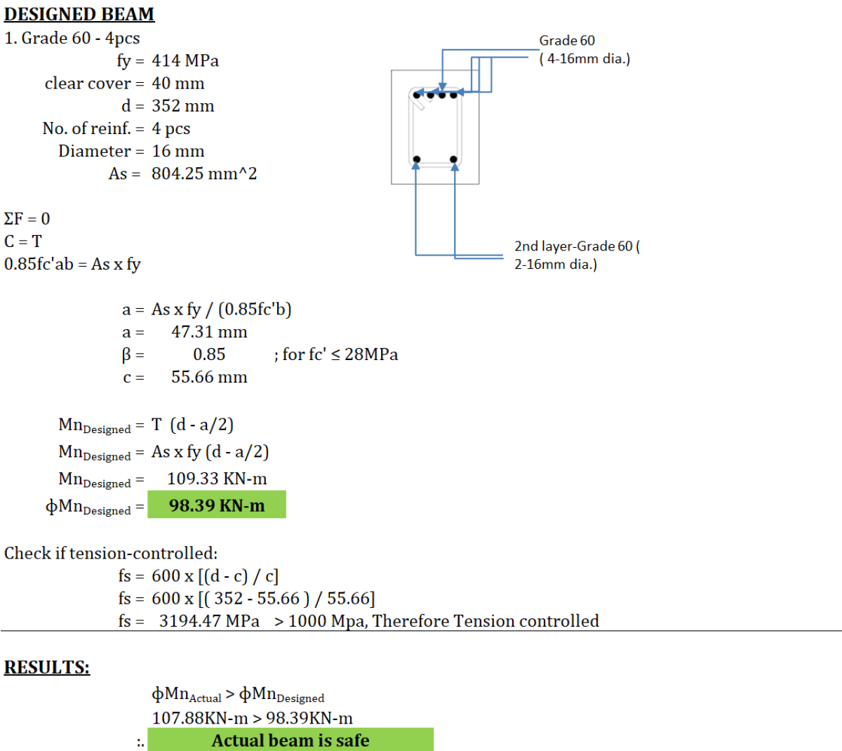
6. Design Comparison
- The "Actual Beam" represents an existing or proposed reinforcement layout
- The "Designed Beam" represents a simplified alternative arrangement
- Comparing their capacities determines if the actual beam is adequate
This is like comparing two different arrangements of support cables in a suspension system - you need to ensure the actual arrangement can handle at least as much load as your minimum design requirement.
Calculation Preview
Full download access to any calculation is available to users with a paid or awarded subscription (XLC Pro).
Subscriptions are free to contributors to the site, alternatively they can be purchased.
Click here for information on subscriptions.
Comments: 1
×
johndoyle-admin
11 months ago
Thanks for your debut contribution I have awarded you a 3 month XLC Pro subscription by way of thanks!