BMREINF9.xls
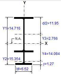
Description
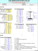
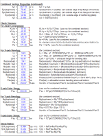
"BMREINF9" is a spreadsheet program written in MS-Excel for the purpose of analysis and code checking of steel members with various types of reinforcement configurations. Specifically, members are analyzed / code checked per the AISC 9th Edition Allowable Stress Design (ASD) Manual. Both actual and allowable stresses are computed, with the final result being a computed "stress ratio" of actual stress/allowable stress. Both the
intermediate and end weld requirements for attaching the reinforcing to the existing member are determined.
This program is a workbook consisting of nine (9) worksheets, described as follows:
Worksheet NameDescription
- Doc - Documentation sheet
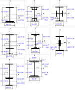
- Member+Plate - Analysis of Existing Member Reinforced with Plate at Bottom
- Member+WT - Analysis of Existing Member Reinforced with WT Section at Bottom
- Member+I-Beam - Analysis of Existing Member Reinforced with I-Beam at Bottom
- Member+4 Angles - Analysis of Existing Member Reinforced with 4 Symmetric Angles
- Member+4 Bars - Analysis of Existing Member Reinforced with 4 Symmetric Round Bars
- Member+2 Plates - Analysis of Existing Member Reinforced with Top & Bottom Plates
- Member+2 WT's(in) - Analysis of Existing Member Reinforced with 2 WT's (webs toed in)
- Member+2 WT's(out) - Analysis of Existing Member Reinforced with 2 WT's (webs toed out)
Program Assumptions and Limitations:
1. This program follows the procedures and guidelines of the AISC 9th Edition Allowable Stress (ASD) Manual (1989).
2. This program uses the database of member dimensions and section properties from the "AISC Shapes Database", Version 3.0 (2001) as well as the AISC 9th Edition (ASD) Manual (1989).
3. This program assumes that existing member is overstressed primarily due to X-axis (strong axis) bending. However, the member may be also subjected to axial load (compression or tension) as well as Y-axis (minor axis) bending. Thus, the maximum resultant stress in the top flange of the composite section is assumed to be compression, while it is assumed to be tension at the bottom of the composite section.
4. This program addresses the concern of existing state of stress for original member by providing input of the "residual" X-axis (major axis) bending moment in the unreinforced member, and in some of the worksheets the "residual" axial load in the unreinforced member. These "residual" loads can be due to dead load alone or a combination of dead load and an assumed portion of the live load. The "residual", the added (new), and the maximum stresses for the beam are calculated as follows:
fa(residual, mem) = P(residual, mem)/A
fa(added) = (P(total)-P(residual, mem))/Ac
fa(reinf) = fa(added)
fa(mem) = fa(residual, mem) + fa(added)
fbx(residual, mem) = Mx(residual, mem)12/Sx
fbx(added, reinf) = (Mx(total)-Mx(residual, mem))12/Sxc(reinf)
fbx(added, mem) = (Mx(total)-Mx(residual, mem))12/Sxc(mem)
fbx(reinf) = fbx(added, reinf)
fbx(mem) = fbx(residual, mem) + fbx(added, mem)
where:A = cross sectional area of existing member alone
Ac = cross sectional area of entire composite section
Sx = section modulus for the existing member alone
Sxc(reinf) = section modulus referenced to extremities of new reinforcing element(s)
Sxc(mem) = section modulus referenced to extremities of existing member
5. This program prompts for the X-axis (strong axis) "cut-off" moment for the beam, which may be input as a value equal to the total design moment, but is more typically equal to the moment capacity of the existing unreinforced member. The "cut-off" moment is the moment used to determine the end weld requirements for the member reinforcing.
6. In this program for members subjected to known loadings consisting of axial load (compression or tension) and/or uniaxial or biaxial bending, both the actual and allowable stress are computed, with the final result being a computed "stress ratio" of actual stress/allowable stress.
7. For cases when the axial load is compression, then it is considered at the top flange of the section but it is not considered at the bottom of the section. When the axial load is tension, then it is not considered at the top flange of the section but it is considered for the bottom of the section.
8. In this program if beam reinforcing runs for full length, then the composite section properties will be used in computing both the actual and the allowable axial compressive stresses. Otherwise, only the properties of the original existing beam are used for reinforcing that does not run for full length of beam. (See Note #9.)
9. When a stiffened element (web) of a member subjected to axial compression is classified as a "slender" element (exceeding non-compact limits) based on local buckling criteria, then the program complies with AISC Appendix B. If the effective length of web for axial compression as determined by AISC Eqn. A-B5-8 is found to be less than the actual web length, then the area of the web to be deducted is assumed as one-half each side of the centroid of the existing beam for determining the effective section properties.
10. This program utilizes an "Allowable Stress Increase Factor" (ASIF) which is a multiplier of any of the calculated allowable stresses Fa, Fbx, and Fby and also the Euler column buckling stresses F'ex and F'ey. It is used and appears only in the stress ratio calculation. Typically a value of 1.0 may be used. However, a value of 1.333 may be used for load combinations which include wind or seismic loads.
11. If a member loaded with axial compression has a maximum slenderness ratio KL*12/r >200, then a message will appear. However, this program does not consider or deem a particular member as "inadequate" based on the slenderness ratio of 200 being exceeded.
12. For the case of combined axial compression with bending, if the calculated value of fa >=F'e (which is not allowed) then a warning (error!) message will appear.
13. When the values of either 'Lx', 'Ly', or 'Lb' are input = 0' (or actually <= 1.0'), this program will use a value = 1.0'.
14. When the area of the top (assumed compression) flange is <= the area of the bottom (assumed tension) flange, then this program will not consider the use of AISC Eqn. F1-8 per Section F1.3 in determining the allowable X-axis bending stress, 'Fbx'.
15. The values of 'Cb', 'Cmx', 'Cmy', 'Kx, and 'Ky' may be calculated (if applicable) by accessing the additional input data to the right of the main page in each of the calculation worksheets. Then, these calculated values can be input under the member design parameters on the main page. (Note: there are equations which very closely approximate the solutions for 'Kx' and 'Ky' obtained using the AISC Code Alignment Charts.)
16. This program does not calculate or check shear or deflection in member.
17. This program does not consider torsion on member.
18. This program does not consider deduction for holes in members subjected to tension.
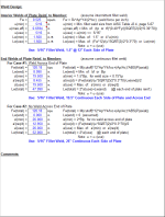
19. In weld design, this program determines the AISC Code minimum fillet weld as well as the maximum effective fillet weld size based on the shear strength of the base material. The weld size used will be the AISC minimum weld size, not to exceed the maximum assumed value for a single pass weld of 5/16". If the maximum effective fillet weld size is less than the actual size used, then the maximum effective fillet weld size is used to determine the actual required weld lengths.
20. This program contains numerous “comment boxes” which contain a wide variety of information including explanations of input or output items, equations used, data tables, etc. (Note: presence of a “comment box” is denoted by a “red triangle” in the upper right-hand corner of a cell. Merely move the mouse pointer to the desired cell to view the contents of that particular "comment box".)
Calculation Reference
AISC
Calculation Preview
Full download access to any calculation is available to users with a paid or awarded subscription (XLC Pro).
Subscriptions are free to contributors to the site, alternatively they can be purchased.
Click here for information on subscriptions.
This workbook is now version 2.0.
By the way for us ASD 9th Edition "die-hards", the "BeamCol(Built-Up)" worksheet is a useful tool for doing AISC Code checks using metric shapes, in that all you need to do is enter a formula in the input cells for each of the dimensions (d, tw, bf, and tf) in millimeters divided by 25.4, and the worksheet will automatically calculate all of the properties for you. Keep in mind that the "fillets" of the member are not considered, so the calculated properties will be very close approximations.

