Beams - shear, moment and displacement
Description
Beam bending tables, also known as beam load tables or simply beam tables, are used by civil engineers as a tool for analyzing and designing structures. These tables typically contain the values for various types of loadings and support conditions that a particular type of beam can safely withstand. They provide an efficient means for determining the appropriate beam size or type to be used in a particular application.
The tables contain key parameters including:
-
Moment of Inertia (I): This is a measure of an object's resistance to changes in its rotation. For beams, it represents the distribution of the material around the neutral axis, which runs through the centroid of the cross-sectional area.
-
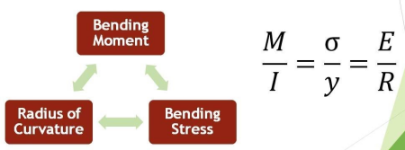
Section Modulus (S): This is a geometric property for a given cross-section used in the design of beams or flexural members. It is directly related to the maximum bending stress that a structural member can withstand.
-
Maximum Bending Moment (M): This is the highest amount of bending moment that the beam will be subjected to under the given loading conditions.
-
Maximum Shear Force (V): This is the highest amount of shear force that the beam will be subjected to under the given loading conditions.
-
Beam Span (L): This is the length of the beam between its supports.
-
Deflection Limits (?): This is the amount the beam will deform under the given loading conditions. There are typically allowable deflection limits based on the beam's application (e.g., for aesthetic or comfort reasons in a building structure).
The use of these tables can greatly simplify the process of beam selection and load capacity calculations, but it's also important to remember that the values are generally conservative estimates. They're based on simple beam theory, which assumes that the beam is perfectly rigid, the material is homogenous and isotropic, and that the loading is perfectly distributed.
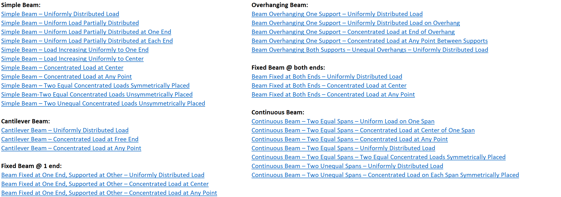
The following load cases are included in this workbook:
Simple Beam:
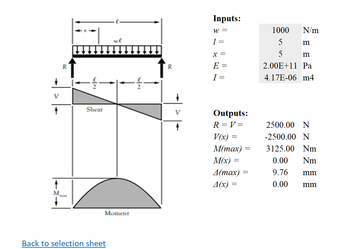
Simple Beam – Uniformly Distributed Load
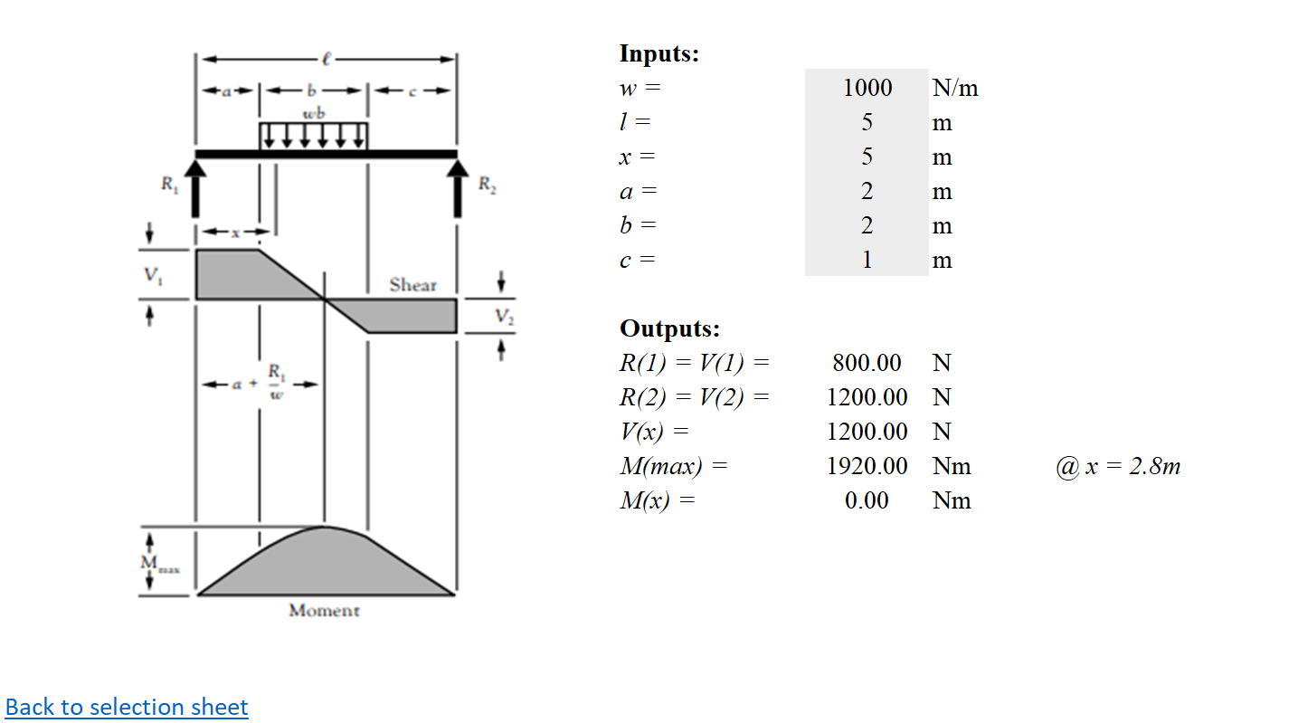
Simple Beam – Uniform Load Partially Distributed
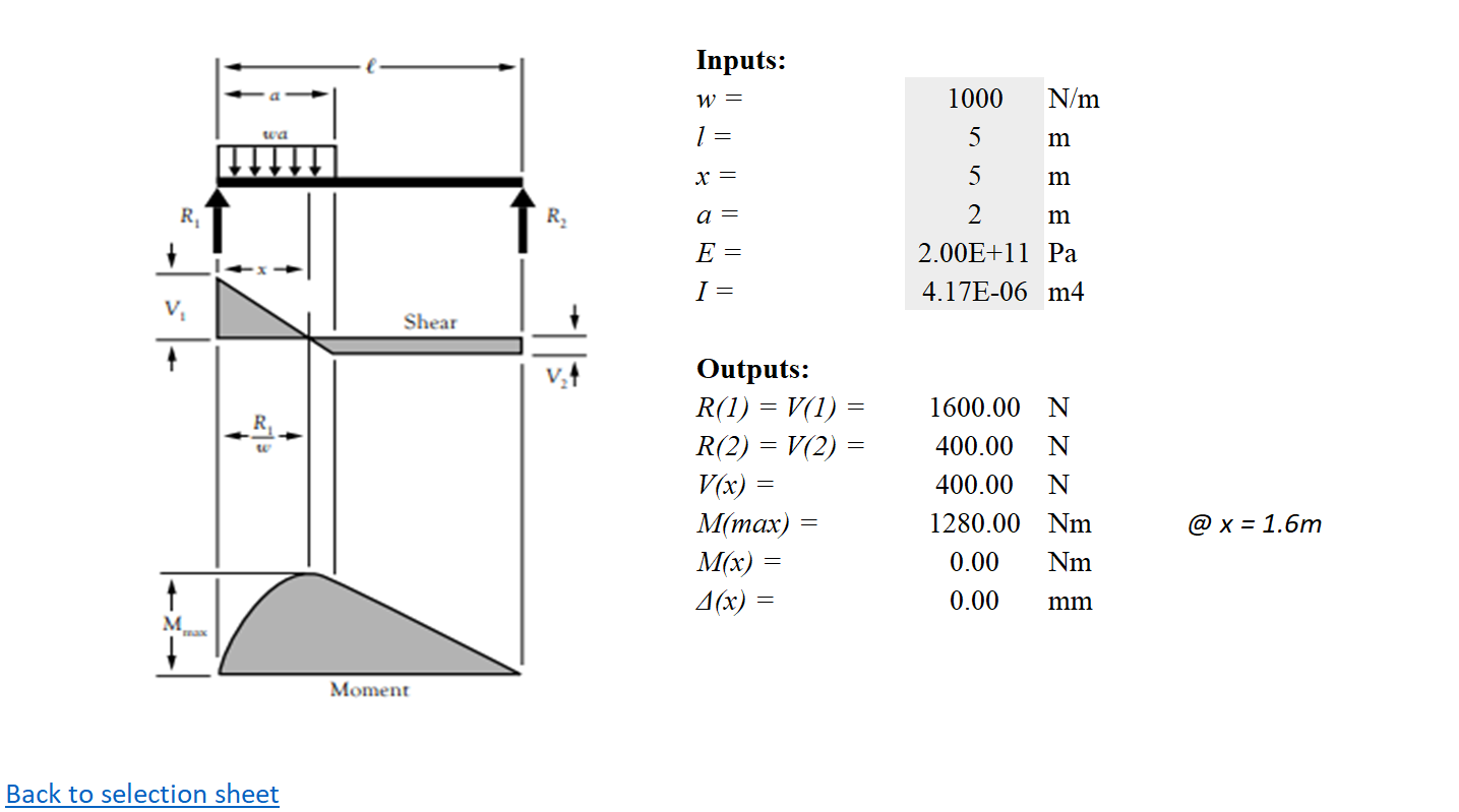
Simple Beam – Uniform Load Partially Distributed at One End
Simple Beam – Uniform Load Partially Distributed at Each End
Simple Beam – Load Increasing Uniformly to One End
Simple Beam – Load Increasing Uniformly to Center
Simple Beam – Concentrated Load at Center
Simple Beam – Concentrated Load at Any Point
Simple Beam – Two Equal Concentrated Loads Symmetrically Placed
Simple Beam-Two Equal Concentrated Loads Unsymmetrically Placed
Simple Beam – Two Unequal Concentrated Loads Unsymmetrically Placed
Cantilever Beam:
Cantilever Beam – Uniformly Distributed Load
Cantilever Beam – Concentrated Load at Free End
Cantilever Beam – Concentrated Load at Any Point
Fixed Beam @ 1 end:
Beam Fixed at One End, Supported at Other – Uniformly Distributed Load
Beam Fixed at One End, Supported at Other – Concentrated Load at Center
Beam Fixed at One End, Supported at Other – Concentrated Load at Any Point
Overhanging Beam:
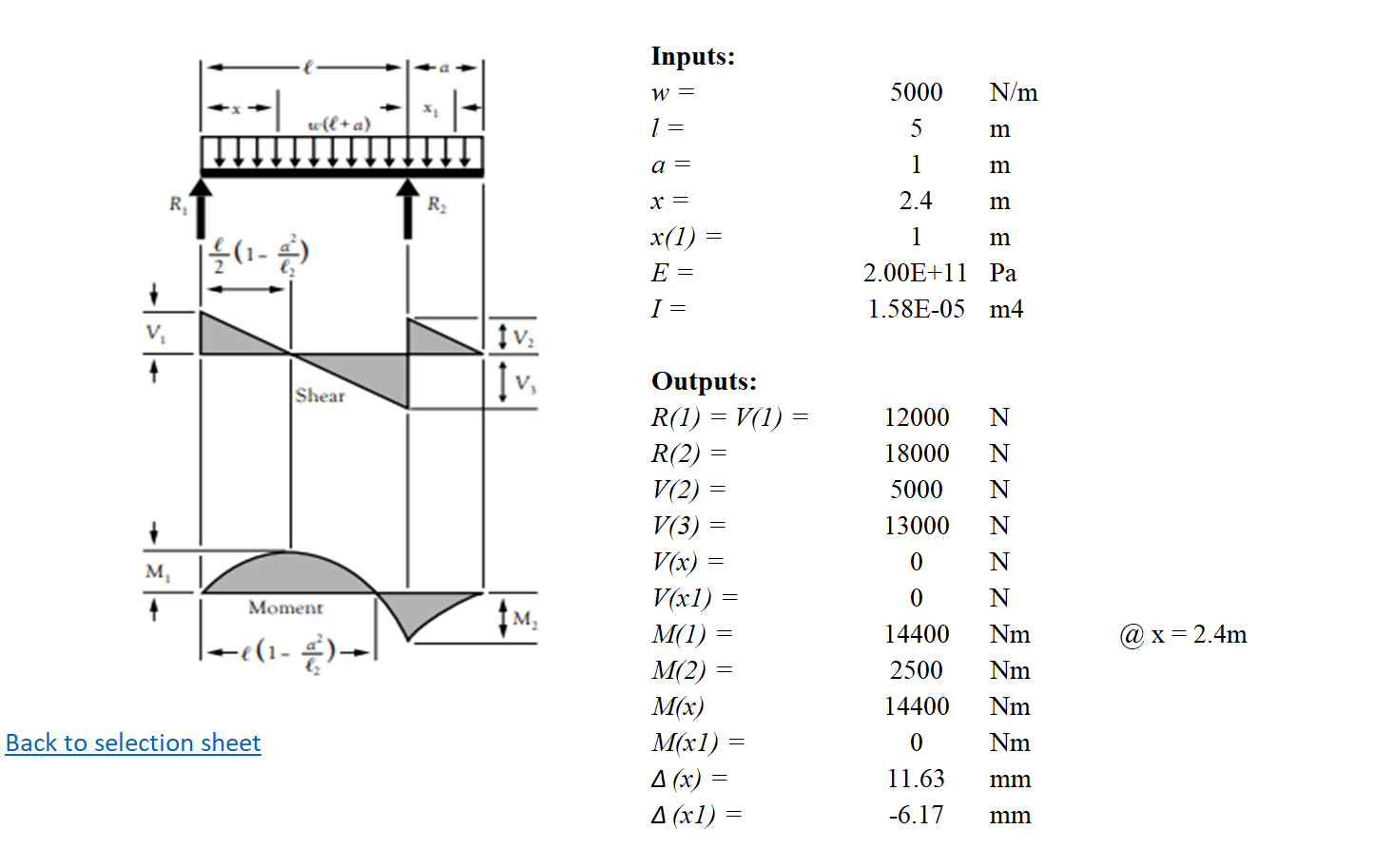
Beam Overhanging One Support – Uniformly Distributed Load
Beam Overhanging One Support – Uniformly Distributed Load on Overhang
Beam Overhanging One Support – Concentrated Load at End of Overhang
Beam Overhanging One Support – Concentrated Load at Any Point Between Supports
Beam Overhanging Both Supports – Unequal Overhangs – Uniformly Distributed Load
Fixed Beam @ both ends:
Beam Fixed at Both Ends – Uniformly Distributed Load
Beam Fixed at Both Ends – Concentrated Load at Center
Beam Fixed at Both Ends – Concentrated Load at Any Point
Continuous Beam:
Continuous Beam – Two Equal Spans – Uniform Load on One Span
Continuous Beam – Two Equal Spans – Concentrated Load at Center of One Span
Continuous Beam – Two Equal Spans – Concentrated Load at Any Point
Continuous Beam – Two Equal Spans – Uniformly Distributed Load
Continuous Beam – Two Equal Spans – Two Equal Concentrated Loads Symmetrically Placed
Continuous Beam – Two Unequal Spans – Uniformly Distributed Load
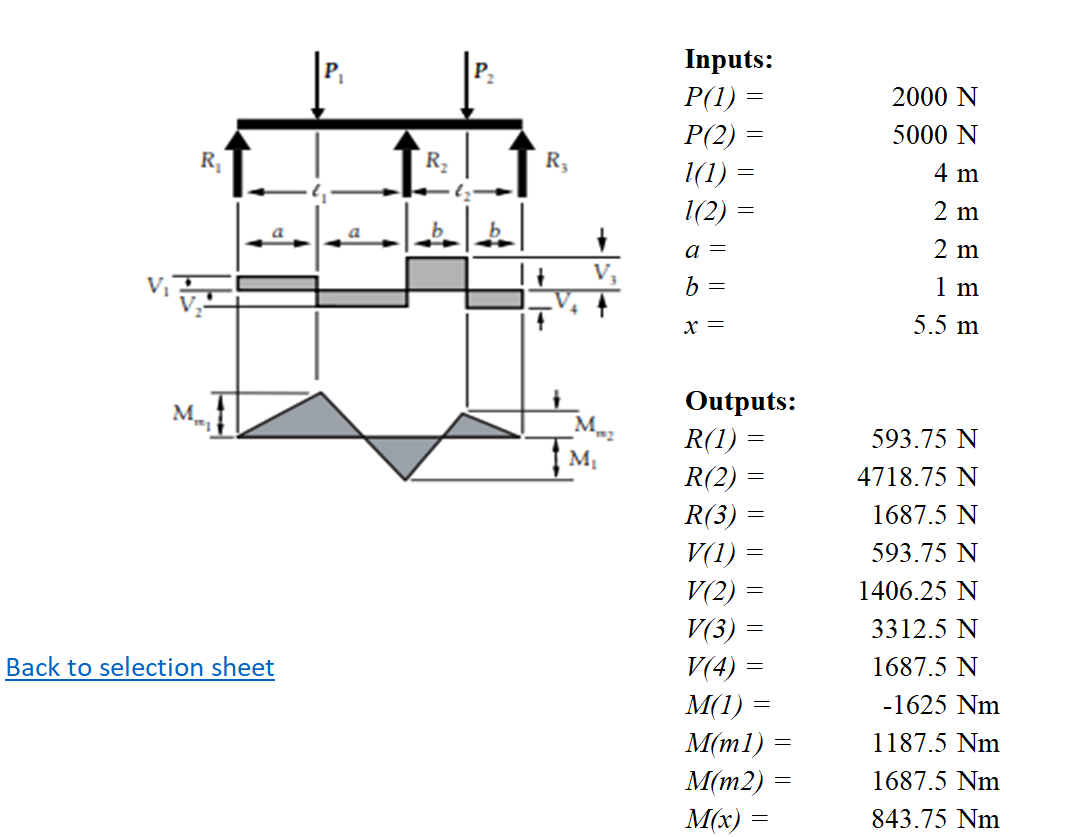
Continuous Beam – Two Unequal Spans – Concentrated Load on Each Span Symmetrically Placed
Calculation Preview
Full download access to any calculation is available to users with a paid or awarded subscription (XLC Pro).
Subscriptions are free to contributors to the site, alternatively they can be purchased.
Click here for information on subscriptions.