
Cold-Formed Channel Purlin Design - Biaxial Bending and Deflection with Sag Rods
 (0/0)

Description
Cold-Formed Channel Purlin Design - Biaxial Bending and Deflection with Sag Rods
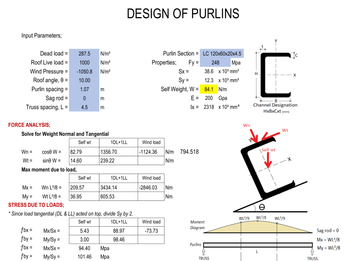
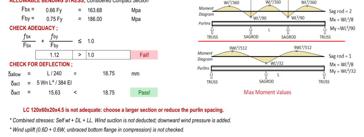
An allowable stress check of a cold-formed lipped-channel purlin on a sloping roof. Dead, roof live and wind loads (NSCP 2015 minimum loads) and the purlin self weight are resolved into components normal and tangential to the roof. Strong- and weak-axis moments are found for no sag rod, one sag rod at mid-span or two at third points, and the combined bending stress (fbx/Fbx + fby/Fby ≤ 1) and the deflection (L/240) are checked. Clear sketches show the load components and the moment diagram for each sag-rod case.
Inputs
- Dead load, roof live load and wind pressure (N/m²; negative wind is suction)
- Roof angle θ, purlin spacing and truss spacing (span) L
- Number of sag rods: 0, 1 or 2 (drop-down)
- Purlin section from a drop-down table of lipped channels, and steel yield strength Fy
Outputs
- Normal and tangential line loads Wn, Wt for self weight, dead + live, and wind
- Moments Mx, My and bending stresses fbx, fby
- Allowable stresses 0.66 Fy and 0.75 Fy and the combined stress ratio with a Pass / Fail verdict
- Mid-span deflection against L/240, and a one-line conclusion
The example is an LC 120×60×20×4.5 purlin at 1.07 m spacing spanning 4.5 m on a 10° roof with no sag rod. After correction it fails the bending check with a combined stress ratio of 1.12; with one sag rod at mid-span the same purlin passes at 0.71. Deflection is 15.63 mm against 18.75 mm allowed. SI units.
Checked and corrected
Every result was recomputed independently. ExcelCalcs made four corrections to the uploaded file (17 November 2026, version 1.1):
- Wind suction no longer reduces the gravity check. The combined strong-axis stress added the full wind suction (−73.73 MPa) to the dead + roof live stress. It is now self weight + dead + roof live, with wind added only when it is a downward pressure. In the example fbx rises from 20.67 MPa to 94.40 MPa and the stress ratio from 0.67 (“Pass!”) to 1.12 (“Fail!”).
- The strong-axis moment with two sag rods is now wL²/8. Sag rods brace only the weak axis; wL²/9 is the moment at the rods, not at mid-span, so Mx was understated by 11% whenever two sag rods were chosen. The label in the moment-diagram sketch is corrected to match.
- The conclusion now follows the checks: it recommends the section only when both the bending and deflection checks pass, and mentions sag rods only when some are selected. It previously read “Therefore use, LC 120x60x20x4.5 … Provide sag rod @ middle of truss” for the failing, no-sag-rod example.
- Two notes added below the conclusion state the load combination used and that wind uplift is not checked.
Please note
- Wind uplift (0.6D + 0.6W) is not checked. Under uplift the bottom flange, which is not braced by the sheeting, is in compression and lateral-torsional buckling must be considered.
- The allowable stresses 0.66 Fy and 0.75 Fy are hot-rolled compact-section values. Cold-formed lipped channels are normally designed to the cold-formed provisions (NSCP 2015 Chapter 5 / AISI S100), which include local and lateral-torsional buckling. The check assumes the top flange is fully braced by the roof sheeting.
- The weak-axis stress from dead + live load uses Sy/2 (load applied at the top flange), as noted on the sheet. The deflection uses dead + live load without self weight (16.58 mm with it in the example, still within L/240).
- The dead-load helper in the hidden columns is not linked to the dead load used; enter the dead load directly.
Calculation Preview
 (0/0)
Full download access to any calculation is available to users with a paid or awarded subscription (XLC Pro).
Subscriptions are free to contributors to the site, alternatively they can be purchased.
Click here for information on subscriptions.

**What needs to change**
- Check each load combination separately (dead + roof live; dead + downward wind + roof live; dead + wind uplift) and report the worst. Wind suction should never reduce the dead + roof live check.
- With two sag rods the strong-axis moment is still wL²/8 at mid-span; wL²/9 is the moment at the rods, as your own sketch shows. The sheet understates Mx by 11% in that case.
- Add the uplift case, where the unbraced bottom flange is in compression.
- Say which code clauses the allowable stresses 0.66 Fy and 0.75 Fy come from, and whether they suit a cold-formed lipped channel (the cold-formed provisions in NSCP 2015 Chapter 5 / AISI S100 would normally apply).
- The conclusion recommends a sag rod at mid-span even when "Sag rod = 0" is chosen.
- Tidy up: the dead-load helper (AE5) adds per-mm unit weights without the thicknesses and is not linked to the dead load used (G7); remove the unused hidden W-shape sheet and the defined names that point to #REF!.
- Add a short statement of the design basis at the top, and say how you checked the results.
What works well: the sketches of the load components and of the moment diagrams for each sag-rod case are clear, and the drop-down lists for section, roof covering and steel grade make the sheet easy to use.
If you upload a corrected version we'll be glad to review it again: a corrected calculation earns a 3-month XLC Pro subscription, and one that follows the guide in full earns 12 months.
We offer guidance for authors on The Good Calculation Guide: [https://www.excelcalcs.com/calcs/good-calc-guide](https://www.excelcalcs.com/calcs/good-calc-guide). We hope that this does not discourage you from trying again and thanks for your interest in the site.
**What we corrected**
- G29, the combined strong-axis stress, no longer subtracts the wind suction from the dead + roof live load. It is now self weight + DL + LL, with wind added only when it is a downward pressure. For your example fbx becomes 94.40 MPa (it was 20.67 MPa).
- AE33:AG33 now use wL²/8 for Mx with two sag rods (it was wL²/9, the moment at the rods). The label in your moment-diagram sketch is changed to match.
- The conclusion in D43 now recommends the section only when both checks pass, and mentions sag rods only when some are chosen.
- Two notes below the conclusion state the load combination used and that wind uplift is not checked.
An independent check of the dead + roof live case gives (5.43 + 88.97)/163.68 + (3.00 + 98.46)/186 = 1.12, which the corrected sheet now shows, so your example LC 120x60x20x4.5 purlin with no sag rod is overstressed by about 12%. With one sag rod at mid-span the same purlin passes at 0.71. Two points remain for a future version: add the wind uplift case (0.6D + 0.6W) with the unbraced bottom flange in compression, and say which code clauses the allowable stresses 0.66 Fy and 0.75 Fy come from, since the cold-formed provisions of NSCP 2015 Chapter 5 / AISI S100 would normally apply to a lipped channel.
Thank you for a clear, compact calculation; the sketches of the load components and of the moment diagrams for each sag-rod case make it easy to follow. I have awarded you a 3-month XLC Pro subscription by way of thanks. Our guidance for authors is in The Good Calculation Guide: [https://www.excelcalcs.com/calcs/good-calc-guide](https://www.excelcalcs.com/calcs/good-calc-guide).