Crane End Stop Weld

Description
Core Engineering Principle: Crane End Stop Design
This calculation follows the principle that when a moving crane bridge hits an end stop, the kinetic energy must be safely absorbed without structural failure of either the crane or the runway system.
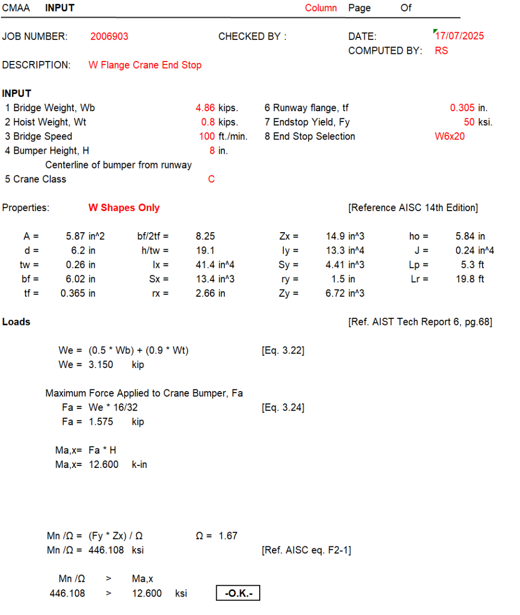
1. Impact Load Calculation
- A moving crane has kinetic energy that must be dissipated when it hits the end stop
- The calculation uses empirical formulas from AIST (Association of Iron & Steel Technology) standards
- The effective weight (We) accounts for the fact that not all crane components contribute equally to impact
- The impact force (Fa) is calculated based on this effective weight and standardized impact factors
2. Dynamic vs. Static Loading
- This isn't just about supporting the crane's weight - it's about absorbing impact energy
- The force applied to the bumper creates a moment (bending force) in the end stop beam
- The moment arm is the height (H) from the runway centerline to where the bumper contacts
3. Beam Bending Analysis
- The end stop beam (W6x20 steel section) must resist the bending moment without yielding
- Uses standard steel design principles: Applied moment (Ma,x) must be less than allowable moment capacity
- The allowable moment uses the plastic section modulus (Zx) and appropriate safety factors (Ω)
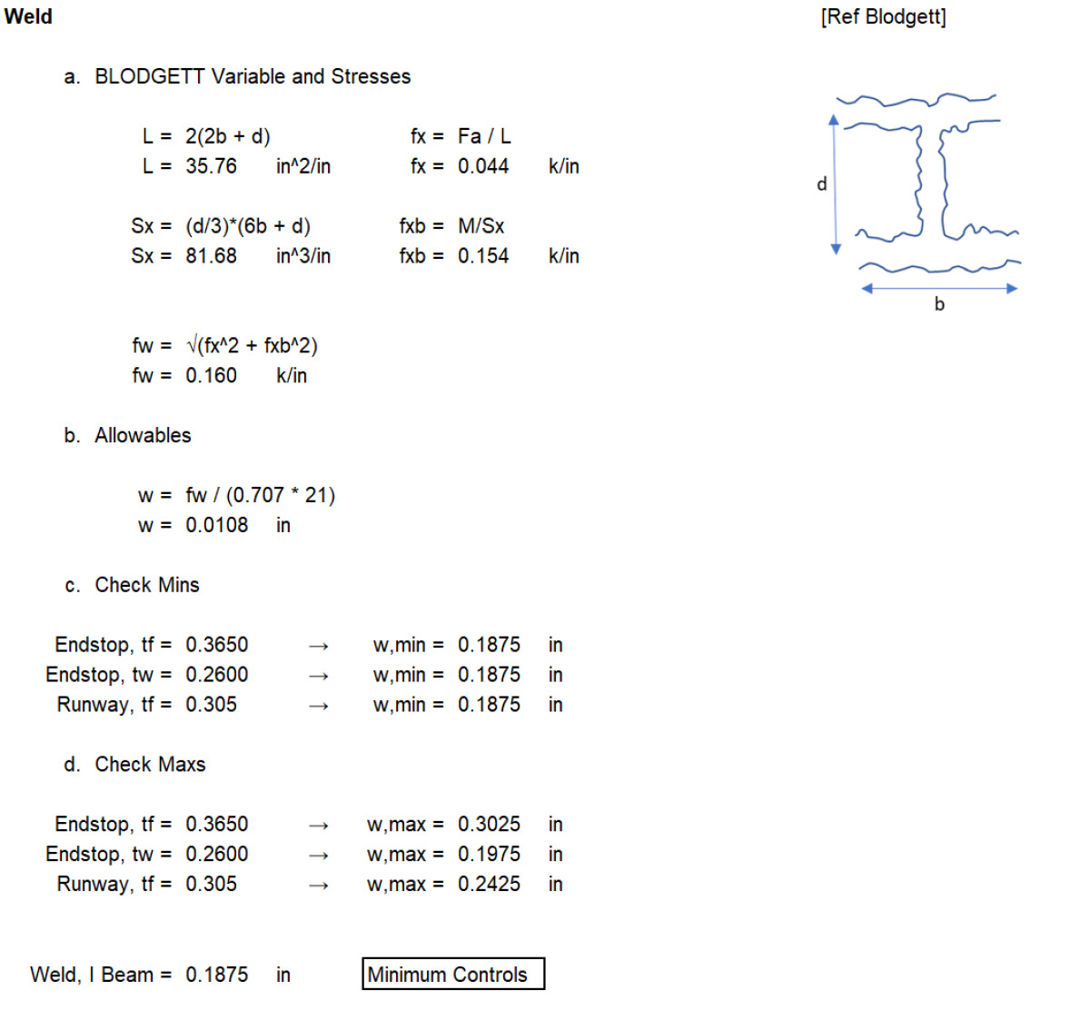
4. Connection Design (Weld Analysis)
- The end stop must be welded to the runway beam strong enough to transfer the impact forces
- Blodgett method analyzes weld stresses considering both direct force and bending moment
- The weld size must be adequate for the calculated stresses but also meet minimum practical requirements
5. Practical Constraints
- Minimum weld sizes based on material thickness (you can't make welds too small to be reliable)
- Maximum weld sizes limited by material thickness (you can't weld thicker than the base metal)
- The final weld size is governed by whichever constraint is most restrictive
6. Crane Classification System
- Different crane classes (A, B, C, D) have different service requirements
- Higher classes need more robust end stops due to more frequent and severe impacts
- The table shows recommended beam sizes for different crane classes
This is essentially designing a "shock absorber" system - the end stop must be strong enough to stop the crane safely without damaging the runway structure, similar to how highway guardrails must absorb vehicle impact energy without failing.
Calculation Preview
Full download access to any calculation is available to users with a paid or awarded subscription (XLC Pro).
Subscriptions are free to contributors to the site, alternatively they can be purchased.
Click here for information on subscriptions.
Comments: 1
×
johndoyle-admin
7 months ago
Thanks for sharing your calculation! I have extended your XLC Pro subscription by 3 months by way of thanks.