RECTBEAM (318-05)
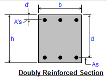
Description
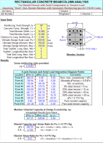
"RECTBEAM" is a spreadsheet program written in MS-Excel for the purpose of analysis/design of rectangular beam or column sections. Specifically, the ultimate moment capacity, bar spacing for crack control, moments of inertia for deflection, beam shear and torsion requirements, and member capacity for flexure (uniaxial and biaxial) with axial load are calculated. There is also a worksheet which contains reinforcing bar data tables.
This version is based on the ACI 318-05 Code.
This program is a workbook consisting of ten (10) worksheets, described as follows:
Doc - This documentation sheet
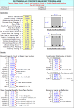
Complete Analysis - Beam flexure, shear, crack control, and inertia
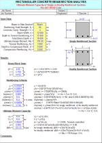
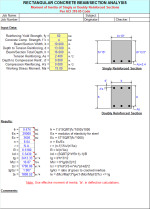
Flexure - Ultimate moment capacity of singly or doubly reinforced beams/sections
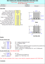
Crack Control - Crack control - distribution of flexural reinforcing
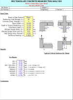
Shear - Beam or one-way type shear
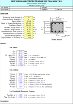
Torsion - Beam torsion and shear
Inertia - Moments of inertia of singly or doubly reinforced beams/sections
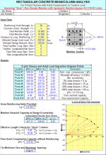
Uniaxial - Combined uniaxial flexure and axial load
Biaxial - Combined biaxial flexure and axial load
Rebar Data - Reinforcing bar data tables
Program Assumptions and Limitations:
1. This program follows the procedures and guidelines of the ACI 318-05 Building Code.
2. This program utilizes the following references:
a. "Design of Reinforced Concrete - ACI318-05 Code Edition", by Jack C. McCormac (7th Ed.)
b. "Notes of the ACI318-05 Building Code Requirements for Structural Concrete", by PCA
3. The "Complete Analysis" worksheet combines the analyses performed by four (4) of the individual worksheets all into one. This includes member flexural moment capacity, as well as shear, crack control, and inertia calculations. Thus, any items below pertaining to any of the similar individual worksheets included in this one are also applicable here.
4. In the "Flexure", "Uniaxial", and "Biaxial" worksheets, when the calculated distance to the neutral axis, 'c', is less than the distance to the reinforcement nearest the compression face, the program will ignore that reinforcing and calculate the ultimate moment capacity based on an assumed singly-reinforced section.
5. In the "Uniaxial" and "Biaxial" worksheets, the CRSI "Universal Column Formulas" are used by this program to determine Points #1 through #7 of the 10 point interaction curve. For the most part, these formulas yield close, yet approximate results. However, these results should be accurate enough for most applications and situations.
6. To account for the fact that the CRSI "Universal Column Formulas" originally utilized f =0.70 for compression, which was applicable up through the ACI 318-99 Code, they have been factored by (0.65/0.70) to account for the reduction in the factor f = 0.65 for compression beginning with ACI 318-02 Code and continuing with the ACI 318-05 Code. This modification has been made to the equations applicable to Points #1 through #7.
7. In the "Uniaxial" and "Biaxial" worksheets, the CRSI "Universal Column Formulas", which are used by this program, assume the use of the reinforcing yield strength, fy =60 ksi.
8. In the "Uniaxial" and "Biaxial" worksheets, this program assumes a "short", non-slender rectangular column with symmetrically arranged and sized bars.
9. In the "Uniaxial" and "Biaxial" worksheets, for cases with axial load only (compression or tension) and no moment(s) the program calculates total reinforcing area as follows:
Ast = (NtbAbt) + (NsbAbs) , where: Abt and Abs = area of one top/bottom and side bar respectively.
10. In the "Uniaxial" and "Biaxial" worksheets, for pure moment capacity with no axial load, the program assumes bars in 2 outside faces parallel to axis of bending plus 50% of the total area of the side bars divided equally by and added to the 2 outside faces, and program calculates reinforcing areas as follows:
for X-axis: As = A's = ((NtbAbt) + (0.50NsbAbs))/2
for Y-axis: As = A's = ((NsbAsb+4Atb) + (0.50(Ntb-4)Atb))/2
11. In the "Uniaxial" and "Biaxial" worksheets, for Point #8 (fPn = 0.1f'cAg) on the interaction curve the corresponding value of fMn is determined from interpolation between the moment values at Point #7 (balanced condition, f = 0.65) and Point #9 (pure flexure, f <= 0.90).
12. In the "Complete Analysis" and "Flexure" worksheets as well as the "Uniaxial" and "Biaxial" worksheets (for Point #9, pure flexure) the program first determines the strain in tension reinforcing (et), then the capacity reduction factor (f),and finally ultimate moment capacity (fMn) based on actual input reinforcing.
a. For et >= 0.005 ("tension-controlled" section): f = 0.90.
b. For fy/Es < et < 0.005 ("transition" section): f = 0.65+0.25(et-fy/Es)/(0.005-fy/Es) < 0.90 (Es=29000 ksi)
c. For et <= fy/Es ("compression-controlled" section): f = 0.65
Note: the ACI 318-05 Code requires that the strain in the tension reinforcing (et) >= 0.004 for both singly and doubly reinforced sections.
13. In the "Uniaxial" and "Biaxial" worksheets, design capacities, fPn and fMn, at design eccentricity, e = Mu12/Pu, are determined from interpolation within the interaction curve for the applicable axis.
14. In the "Biaxial" worksheet, the biaxial capacity is determined by the following approximations:
a. For Pu >= 0.1f'cAg, use Bresler Reciprocal Load equation:
1/fPn = 1/fPnx + 1/fPny - 1/fPo
Biaxial interaction stress ratio, S.R. = Pu/fPn <= 1
b. For Pu < 0.1f'c*Ag, use Bresler Load Contour interaction equation:
Biaxial interaction stress ratio, S.R. = (Mux/fMnx)^1.15 + (Muy/fMny)^1.15 <= 1
15. The "Rebar Data" worksheet contains tables of reinforcing bar data which include various bar properties, reinforcing bar areas based on spacing, and various plain welded wire fabric properties.
16. This program contains numerous “comment boxes” which contain a wide variety of information including explanations of input or output items, equations used, data tables, etc. (Note: presence of a “comment box” is denoted by a “red triangle” in the upper right-hand corner of a cell. Merely move the mouse pointer to the desired cell to view the contents of that particular "comment box".)
Calculation Reference
ACI 318-05
Calculation Preview
Full download access to any calculation is available to users with a paid or awarded subscription (XLC Pro).
Subscriptions are free to contributors to the site, alternatively they can be purchased.
Click here for information on subscriptions.
While I was at it, I also "cleaned up" some display issues in a few of the illustrations where some input values were being displayed.
Also, in the "Biaxial" worksheet and under the heading of "Tie Min. Size & Max. Spac:", the program was supposed to be only referencing the input cells for the longitudinal bar sizes in Cells D18 and D20. However, it was also inadvertently referencing Cell D19, which pertains to the total number of side reinforcing bars.
I have made the necessary corrections to the above mentioned items.
While I was at it, I decided to add a new worksheet to this workbook. The "Slenderness (Sidesway)" worksheet can be used to analysis the slenderness effects for a single, unbraced column subject to sidesway. This worksheet is very well suited for the quick slenderness analysis of a pier of a foundation, where there is either no supporting soil around the pier or where the soil is considered inadequate to provide continuous lateral support for the pier.
This workbook is now version 1.3.
I have corrected this typo error, and the version of this workbook is now 1.2.
For any of the rest of you who might not have been aware of this change, starting with ACI 318-02 based on the actual reinforcing that is used in the cross section, one has to first calculate the strain in the tension reinforcing, then calculate the "phi" factor, and finally calculate the ultimate moment capacity for the cross section. What this means is that one can no longer directly solve for the required tension reinforcing for a given ultimate design moment, as was always done in the past when "phi" was = 0.90. Thus, you'll see in the workbook that one of the changes that I made was to eliminate the worksheet that directly solved for the required tension reinforcing. However, in the first 2 worksheets that deal with flexure, off of the calculation page to the right, the program calculates the required reinforcing for the given moment (assuming "phi" = 0.90) to give the user a hint of the amount of required reinforcing to input into the calculation.
Another change in the recent codes is that the maximum flexural reinforcing ratio is no longer controlled by 3/4 of the balanced reinforcing ratio, rho(max) = 0.75*rho(bal). It is now controlled by limiting the strain in the tension reinforcing to a minimum value of 0.004. When the calculated strain is >= 0.005, then it is a "tension controlled" section and the "phi" factor = 0.90.
I apologize for this oversight on my part, but I'm consoled to some degree to have learned that I was far from being the only one who had missed this change in the Codes.
This same correction was also made in the shear calculation portions of the "Complete Analysis" and "Torsion" worksheets as well. This workbook is now version 1.1.


• First, while writing his own MathCAD sheet and using mine as a go-by, Chuck Hope ran across a units 'glitch' in the 'Shear' worksheet for the maximum spacing, 's(max)', of the shear reinforcing. The text in the associated comment box did correctly reflect the provisions of the ACI Code for maximum spacing. However, it turned out that I had forgotten to convert the units from pounds to kips in the actual programming. Thus, the result was not correct for the special case where the provided shear reinforcing capacity, (phi)Vs, was greater than 4*(phi)*SQRT(f'c*1000)*b*d/1000. I made the necessary correction which was required in all 3 workbooks.
• Next, while using the 'Torsion' worksheet in the 'RECTBEAM (318-11).xls' workbook, I noticed that the sketch was not correct. I had the dimension lines for the terms 'xo' and 'yo' shown incorrectly. The dimension lines should have been shown from the center to center of the transverse shear reinforcing (ties). I made these corrections to all 3 workbooks. By the way, the calculations for 'xo' and 'yo' were correct, it was just a problem with the sketch.
• Finally, I had occasionally received requests to provide a copy of the original CRSI 'Universal Column Formulas' that CRSI published in their Handbook up through the version that addressed the ACI 318-99 Code. (I make use of those formulas, with modifications as required, in the 'Uniaxial' and 'Biaxial' worksheets.) Later versions of the CRSI Handbook from 2002 to present had the formulas omitted. So, I added a worksheet in all 3 workbooks that includes the original CRSI 'Universal Column Formulas' for reference.