AISC H3 Members Subject to Torsion and Combined Torsion, Flexure, Shear, And/Or Axial Force

Description
Core Engineering Principle: Combined Stress Interaction in Steel Members
This calculation follows the AISC Steel Construction Manual 15th Edition principle that when a structural member is subjected to multiple types of forces simultaneously (torsion, bending, shear, and axial), these forces interact with each other and must be checked using interaction equations to prevent failure.
1. Multi-Force Loading Concept Real-world structural members rarely experience just one type of loading. This calculation addresses the scenario where a member experiences:
- Major axis bending moment (Mx): Bending about the strong axis
- Minor axis bending moment (My): Bending about the weak axis
- Torsion moment (T): Twisting about the longitudinal axis
- Axial force (P): Compression or tension along the member length
- Shear force (V): Forces perpendicular to the member axis
2. Interaction Effect Principle
- When multiple forces act together, they don't simply add up linearly
- The combined effect can be more severe than the sum of individual effects
- Each force type uses up some of the member's capacity, leaving less available for other forces
- The interaction is expressed as ratios: Applied force / Allowable force
3. Threshold-Based Equation Selection The calculation uses threshold values to determine which interaction equations apply:
- Torsion ratio (Tr/Tc) ≥ 0.2: Torsion is significant, use full interaction equation H3-6
- Axial ratio (Pa/Pn) < 0.2: Axial force is small, use simplified approach H1-1b
- Different equations apply based on which forces dominate the behavior
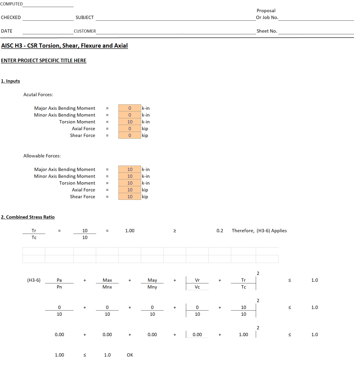
4. Combined Stress Ratio (CSR) Method The interaction equation H3-6 takes the form:
(Pa/Pn) + (Mx/Mnx) + (My/Mny) + (V/Vc) + (T/Tc)² ≤ 1.0
Key aspects:
- Each term represents the utilization ratio for that force type
- Torsion is squared (T²) because torsional effects are more severe in interaction
- The sum must be ≤ 1.0 for the member to be adequate
- Each ratio represents how much of that capacity is being used
5. Capacity Utilization Concept
- Pa/Pn = 0.00: Using 0% of axial capacity
- Mx/Mnx = 0.00: Using 0% of major axis bending capacity
- My/Mny = 0.00: Using 0% of minor axis bending capacity
- V/Vc = 0.00: Using 0% of shear capacity
- T/Tc = 1.00: Using 100% of torsional capacity
6. Safety Verification
- Total interaction ratio = 1.00 ≤ 1.0 ✓ "OK"
- This means the member is right at its capacity limit for pure torsion
- Any additional loading would cause the interaction ratio to exceed 1.0, indicating failure
7. Design Philosophy This approach recognizes that structural members in real buildings experience complex loading. Rather than designing for each force type independently, the engineer must consider how they work together. It's like a person carrying multiple bags - you can't carry your maximum weight in each hand simultaneously; the combined load must be manageable.
In this specific case, the member is experiencing pure torsion (twisting) at its full capacity, with no other forces present. The calculation confirms this loading condition is acceptable per AISC standards.
Calculation Preview

Full download access to any calculation is available to users with a paid or awarded subscription (XLC Pro).
Subscriptions are free to contributors to the site, alternatively they can be purchased.
Click here for information on subscriptions.