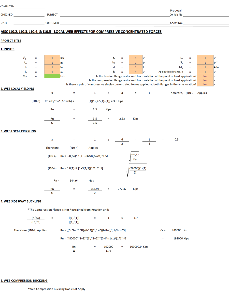
AISC J10.2 through J10.5 Local Web Effects for Compressive Concentrated Forces

Description
This follows AISC Steel Construction Manual 15th Edition. Used for the local web effects on w-sections.
Core Engineering Principle: Connection Element Strength Evaluation
This calculation follows the AISC Steel Construction Manual 15th Edition principle that connection elements (like plates, angles, and gussets) must be checked for multiple failure modes to ensure they can safely transfer forces between structural members.
1. Multiple Failure Mode Analysis The calculation systematically checks different ways the connection element could fail per AISC Chapter J4:
- Tensile yielding: Material reaches yield strength over full cross-section
- Tensile rupture: Material breaks at reduced (net) cross-section due to bolt holes
- Shear yielding: Material yields in shear across the gross area
- Shear rupture: Material tears in shear across the net area
- Block shear: Combined tearing and shearing failure mode
- Compression buckling: Element buckles under compression
2. Gross vs. Net Area Concept
- Gross area (Ag): Full cross-sectional area of the element
- Net area (An): Reduced area after subtracting bolt holes
- Effective area (Ae): Net area modified for stress concentration effects
- Different failure modes use different areas depending on how the failure occurs
3. Material Property Utilization
- Yield strength (Fy): Used for yielding calculations (material reaches elastic limit)
- Ultimate strength (Fu): Used for rupture calculations (material actually breaks)
- The 0.6 factor for shear recognizes that shear strength is typically 60% of tensile strength
4. Safety Factor Application (AISC ASD Method)
- Ω (Omega): Safety factor that varies by failure mode per AISC specifications
- Yielding modes use Ω = 1.67 (less critical, gives warning)
- Rupture modes use Ω = 2.0 (more critical, sudden failure)
- Applied as: Allowable capacity = Nominal capacity / Ω
5. Block Shear - Complex Failure Mode
- This is a combined failure mechanism where material can tear along one path while shearing along another
- The calculation checks two possible combinations and uses the lesser value per AISC J4-5
- Common in connections where forces create both tension and shear stresses
6. Governing Failure Mode
- The calculation computes capacity for all possible failure modes
- The lowest capacity controls the design (indicated by "Controls")
- In this example, shear yielding at 12.93K is the limiting factor
7. Compression Considerations
- For compression members, buckling (not material strength) often governs
- The slenderness ratio (Lc/r) determines if the element is short enough to reach yield before buckling
- If Lc/r ≤ 25, the element is considered "short" and material strength governs per AISC J4-6
This is like analyzing a chain - you need to check every possible way each link could fail (stretching, breaking, bending) because the chain is only as strong as its weakest failure mode. The engineer must verify that the connection element can handle the applied loads without failing in any of these modes according to AISC Steel Construction Manual 15th Edition standards.
Calculation Preview
Full download access to any calculation is available to users with a paid or awarded subscription (XLC Pro).
Subscriptions are free to contributors to the site, alternatively they can be purchased.
Click here for information on subscriptions.