
Retaining Wall Detailing Calculation Excel Sheet.xlsx
 (0/0)
(0/0)
Description
Cantilever RC Retaining Wall — Design & Independent Validation
What this spreadsheet does
This workbook is the complete structural design of a cantilever reinforced-concrete retaining wall for a site labelled “Thapar, Derabassi” (India). It runs the full workflow across three sheets:
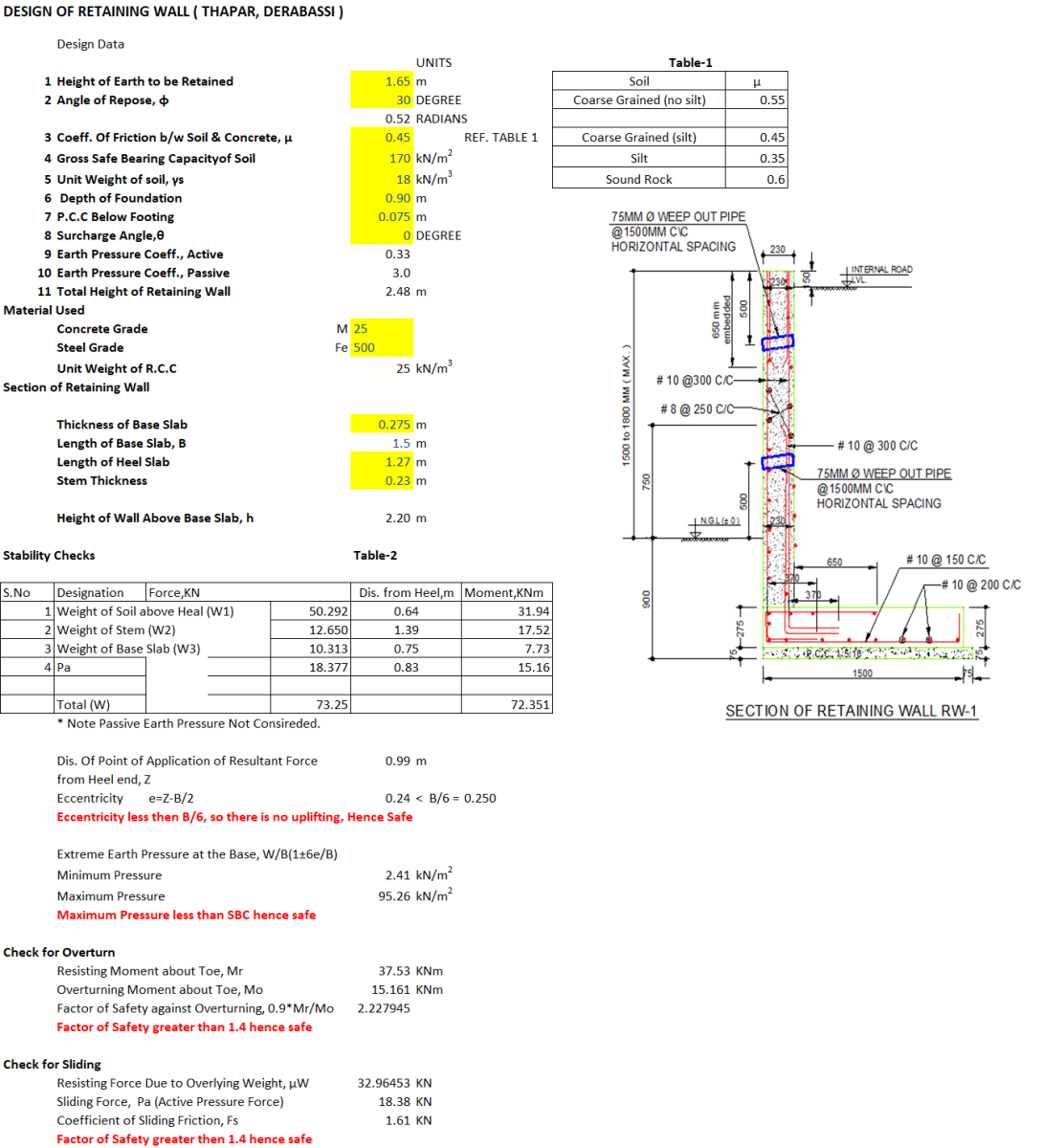
- STABILITY CHECKS — geometry, soil and material data; earth-pressure coefficients; self-weights; then the rigid-body checks for bearing pressure / eccentricity, overturning and sliding.
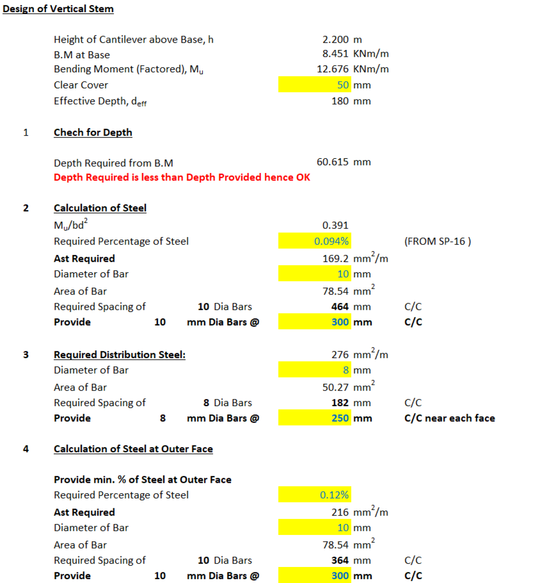
- DESIGN STEM — the vertical wall as a cantilever: factored base moment, depth check, main flexural steel, distribution steel and outer-face steel.
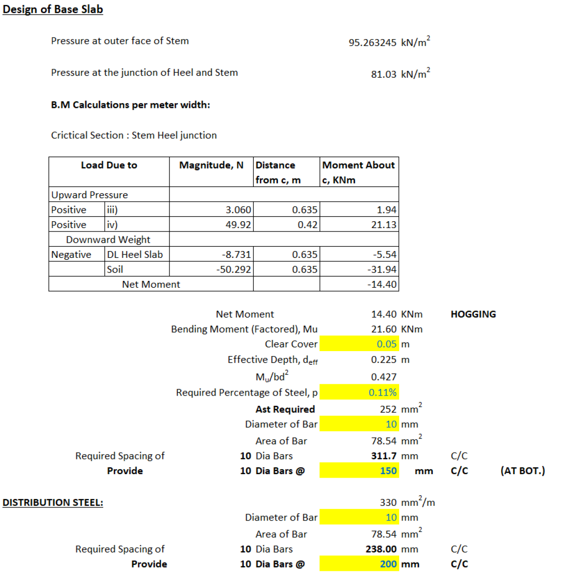
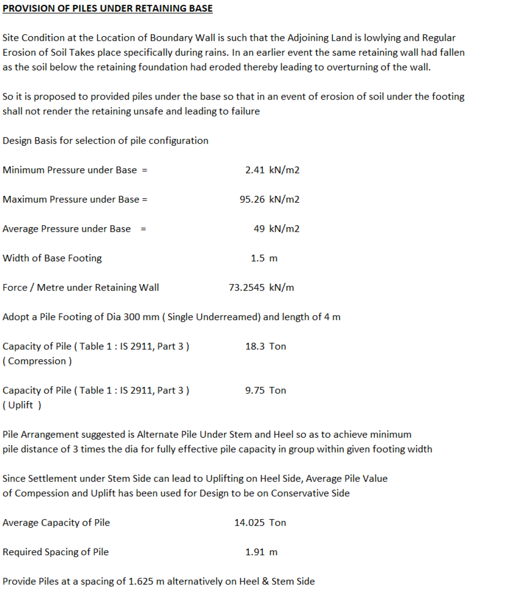
- DESIGN TOE & HEEL SLAB — the base slab (the toe length works out to zero, so this is effectively the heel slab), plus a supplementary under-reamed pile scheme in case the founding soil erodes.
Key inputs
- Retained height = 1.65 m; angle of repose φ = 30°; γsoil = 18 kN/m³
- Safe bearing capacity = 170 kN/m²
- Concrete M25, steel Fe500
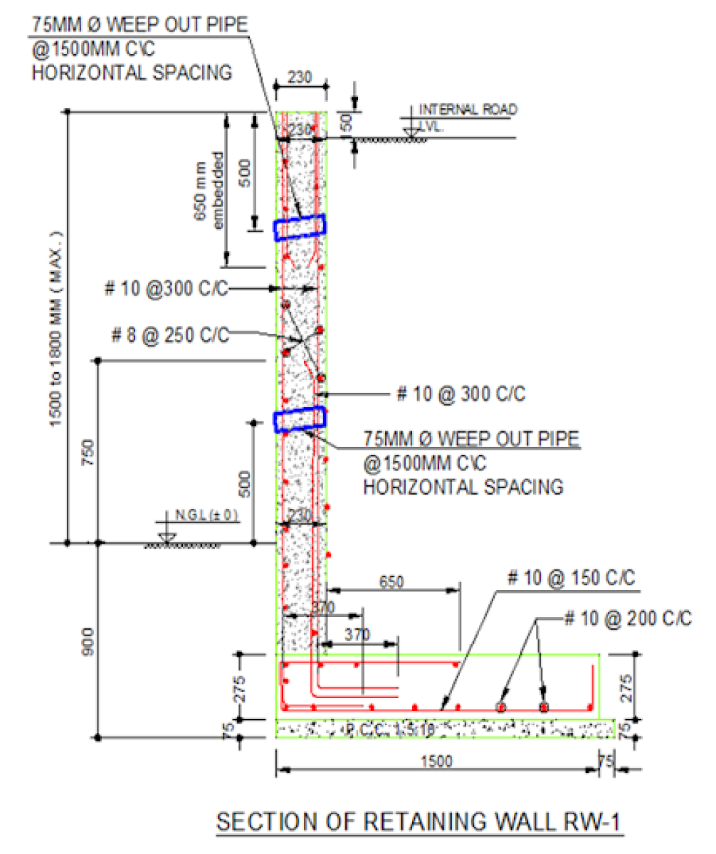
- Base 1.5 m wide × 0.275 m thick; stem 0.23 m; heel 1.27 m
- Load factor 1.5 on service moments
Codes of practice followed
- IS 456:2000 — limit-state RC design; stem uses the limiting-moment factor 0.138·fck·b·d² for Fe500, and 0.12% minimum steel for HYSD bars.
- SP-16 (Design Aids for RC to IS 456) — required steel percentages read from the tables.
- Rankine earth-pressure theory (sloped-surcharge form) — Ka = 0.333, Kp = 3.
- IS 2911 (Part 3) — under-reamed pile capacities (Table 1).
Independent validation
Every governing figure was recomputed from the raw inputs in an independent engine. All stored results reproduce exactly, with no formula errors (#REF/#VALUE) and a number chain that ties out end to end.
| Check | Sheet value | Recomputed | Verdict |
|---|---|---|---|
| Ka / Kp | 0.333 / 3.0 | 0.333 / 3.0 | OK |
| Total vertical load W | 73.25 kN | 73.25 kN | OK |
| Eccentricity e (< B/6 = 0.25) | 0.238 m | 0.238 m | OK — no tension |
| Max base pressure (< 170 SBC) | 95.26 kN/m² | 95.26 kN/m² | OK |
| FoS overturning (> 1.4) | 2.23 | 2.23 | OK |
| FoS sliding (> 1.4) | 1.61 | 1.61 | OK |
| Stem Mu / depth required (< 180 provided) | 12.68 kNm / 60.6 mm | 12.68 kNm / 60.6 mm | OK |
| Heel Mu | 21.60 kNm | 21.60 kNm | OK |
This proves the arithmetic and formula wiring are internally consistent and error-free. It does not by itself prove the engineering method is correct — the four points below are methodology observations for an engineer to confirm.
Engineering observations (not spreadsheet errors)
- Overturning resisting moment. Mr is taken as W·(B−Z), but Z already contains the active-thrust overturning moment, so overturning is effectively subtracted from the resisting side. The pure resisting moment is 52.7 kNm, giving FoS ≈ 3.13 rather than 2.23. The result is conservative, so the “Pass” still holds, but it is not the textbook formula.
- Stem moment credits passive pressure. The stem base moment subtracts a passive (Kp) term of about 2.2 kNm, which reduces the design moment (unconservative) and contradicts the stability sheet, which states that passive earth pressure is not considered.
- Minimum steel. Stem main bars 10 mm @ 300 give ≈262 mm² against a 0.12% minimum of 276 mm²; stem distribution 8 mm @ 250 (≈201 mm²) is below the 276 mm² required. Both fall marginally short of the IS 456 minimums as written.
- Toe length = 0. B − heel − stem = 1.5 − 1.27 − 0.23 = 0, so the wall has no toe projection and the “toe & heel” sheet is really just the heel. Worth confirming this is intended.
Summary: the workbook computes cleanly and passes all stability and design checks; the four items above are method choices worth an engineer’s review before issue.
Calculation Preview
 (0/0)
(0/0)
Full download access to any calculation is available to users with a paid or awarded subscription (XLC Pro).
Subscriptions are free to contributors to the site, alternatively they can be purchased.
Click here for information on subscriptions.