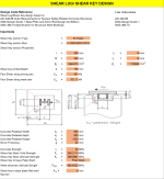
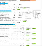
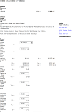
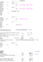
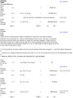
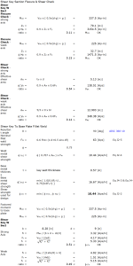
Shear Lug Calculations BP1.xlsx
Description
Shear lugs, also known as shear keys, are used to transfer shear forces between a base plate and a supporting concrete foundation in structural applications. The design of shear lugs is typically governed by the American Concrete Institute (ACI) code, specifically ACI 318, which provides guidelines for designing concrete structures and their components. Here's a summary of the key steps involved in calculating and designing shear lugs for base plates using the ACI code:
-
Determine Shear Forces: Calculate the applied shear force (V) acting on the base plate, considering the load combinations and factored loads specified in the relevant building code or standard.
-
Check Base Plate Capacity: Before proceeding with the shear lug design, ensure that the base plate itself has sufficient capacity to transfer the applied shear force. If the base plate cannot handle the shear, consider resizing or strengthening it.
-
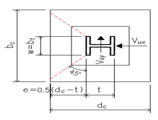
Shear Lug Geometry: Determine the dimensions of the shear lug, such as length (L), width (B), and height (H). The dimensions should be selected based on the available space, practicality, and constructability, as well as providing adequate shear resistance.
-
Shear Friction: Calculate the shear friction capacity (V_n) of the shear lug-concrete interface using the ACI 318 equation: V_n = λ * μ * A_c * f'_c, where λ is the modification factor for the concrete strength, μ is the coefficient of friction, A_c is the contact area between the shear lug and the concrete, and f'_c is the specified compressive strength of the concrete. Ensure that the shear friction capacity is greater than or equal to the applied shear force (V).
-
Concrete Bearing Capacity: Check the concrete bearing capacity around the shear lug to ensure that the concrete does not fail due to localized stress concentration. Calculate the concrete bearing stress (σ_c) and compare it to the allowable bearing stress (0.85 * f'_c) as per ACI 318. If the bearing stress exceeds the allowable value, consider increasing the shear lug size or adding more shear lugs.
-
Shear Lug Steel Reinforcement: Design the steel reinforcement for the shear lug to resist the applied shear force. This typically includes providing adequate shear and flexural reinforcement, as well as anchorage and development lengths for the reinforcing bars, in accordance with ACI 318 requirements.
-
Constructability and Detailing: Ensure that the designed shear lug can be practically constructed and is compatible with the overall base plate and foundation details. Provide clear and accurate drawings and specifications for the fabrication and installation of the shear lug, including dimensions, materials, and reinforcement.
In summary, the calculation and design of shear lugs for base plates using the ACI code involve determining the applied shear force, checking the base plate capacity, selecting the shear lug geometry, calculating the shear friction and concrete bearing capacities, designing the steel reinforcement, and ensuring constructability and proper detailing. Proper design of shear lugs ensures the safe and effective transfer of shear forces between the base plate and the supporting concrete foundation.
Calculation Preview
Full download access to any calculation is available to users with a paid or awarded subscription (XLC Pro).
Subscriptions are free to contributors to the site, alternatively they can be purchased.
Click here for information on subscriptions.

