
Steel Beam-Column Interaction Check - AISC 360-10 (LRFD)
 (0/0)
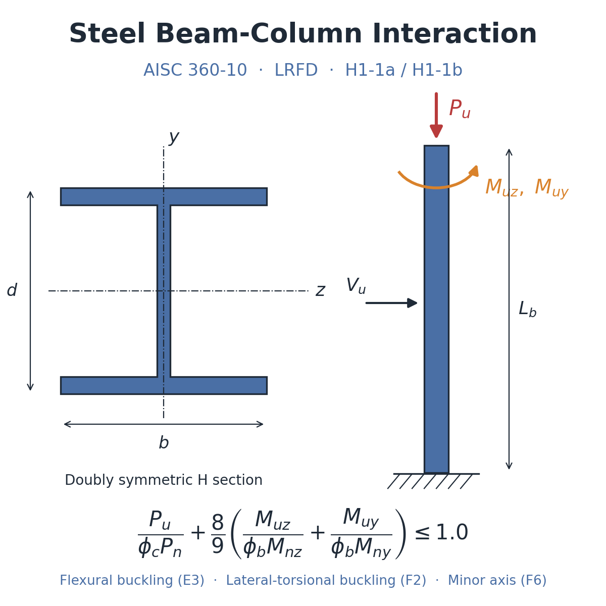
Description
Steel Beam-Column Interaction Check – AISC 360-10 (LRFD)
An LRFD check of a doubly symmetric steel H-section beam-column to AISC 360-10, in SI units. From the section dimensions it calculates the section properties, the flexural buckling strength (Chapter E3), the major-axis flexural strength including lateral-torsional buckling in all three zones (F2), the minor-axis flexural strength (F6) and the combined axial and biaxial bending interaction (H1-1a or H1-1b, chosen automatically from Pu/φPn), with a shear check. The governing equations are displayed beside the working.
Inputs
- Section depth d, flange width b, web thickness tw and flange thickness tf (mm)
- Factored axial load Pu, shears Vuy, Vuz (kN) and moments Muz, Muy (kN·m)
- Elastic modulus E and yield stress Fy (MPa)
- Unbraced lengths Lb (also used as Lx) and Ly, effective length factors Kx, Ky, and Cb
Outputs
- Section properties: A, Ix, Iy, S, Z, J, rts, Lp, Lr
- Slenderness KL/r, Fe, Fcr and the design axial strength φPn
- Major-axis Mn (plastic, inelastic or elastic lateral-torsional buckling) and minor-axis Mny
- The interaction ratio from the governing equation and an ADEQUATE / FAIL verdict
- A shear stress check
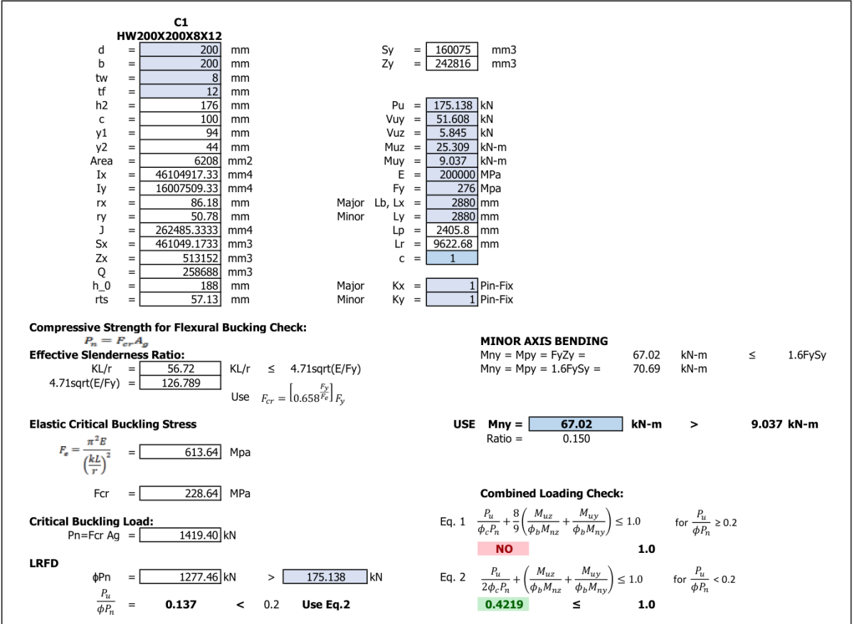
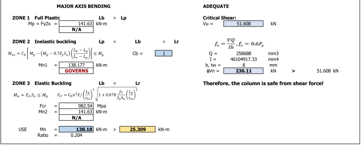
The example is an HW 200 × 200 × 8 × 12 section in Fy 276 MPa steel, 2,880 mm long; Pu/φPn = 0.137, so H1-1b governs with an interaction ratio of 0.422 (adequate).
Checked and corrected
Every result was recomputed independently. ExcelCalcs made eight corrections to the uploaded file (17 November 2026, version 1.1):
- The interaction equations now apply φb = 0.9 to Mnz and Mny, as the displayed equations show. The original divided by the nominal strengths. The example's ratio rises from 0.387 to 0.422.
- The final verdict now tests whichever equation governs. It tested H1-1b only, so it reported “FAIL” for every member with Pu/φPn ≥ 0.2. H1-1a now applies from exactly 0.2 (previously neither equation was evaluated at 0.2), and the comparison signs beside the two equations now belong to their own equation.
- The bending ratios and comparisons for each axis now use φbMn: major axis 0.183 → 0.204, minor axis 0.135 → 0.150.
- The column strength now has the elastic branch Fcr = 0.877Fe for KL/r above 4.71√(E/Fy). No change for the example (KL/r = 56.7).
- The minor-axis section properties Sy and Zy now use the flange width b instead of the depth d, and Lp now uses the E and Fy cells instead of typed values. No change for the example, where b = d.
- The minor-axis strength no longer applies a lateral-torsional buckling reduction, which does not occur in minor-axis bending (F6); Mny = min(FyZy, 1.6FySy) = 67.02 kN·m. The unused step and its equation were removed.
- The major-axis strength is now capped at Mp in zones 2 and 3, as the displayed equations require (this matters when Cb > 1); the zone 3 value shown for the example becomes 141.63 kN·m instead of 453.00 kN·m (zone 2 governs, 138.18 kN·m). The zone selection no longer fails when Lb equals Lr, and it now works in any version of Excel.
- The minor-axis labels in the elastic moment check at the foot of the sheet now read “Minor Axis” and Mny instead of “Major Axis” and Mnz.
Please note
- The section is assumed compact and non-slender; flange and web slenderness are not checked.
- The shear check limits the elastic shear stress VQ/(I·tw) to 0.6Fy rather than using AISC G2 (0.6FyAwCv). It is conservative for the example (236 kN against 265 kN to G2).
- Cb and the K factors are entered by hand; the K table beside the sheet is for guidance only. The example uses K = 1.0. Lb is also used as the major-axis buckling length.
- The equation box beside Fcr shows only the inelastic form; the cell now switches to 0.877Fe for slender members.
- Rows 72 to 84 repeat the bending check with an elastic FyS capacity for information.
Calculation Preview
 (0/0)
Full download access to any calculation is available to users with a paid or awarded subscription (XLC Pro).
Subscriptions are free to contributors to the site, alternatively they can be purchased.
Click here for information on subscriptions.

**What needs to change**
- Apply φb = 0.9 to Mnz and Mny in both interaction equations, as your displayed equations show (the example gives 0.387 where 0.422 is correct).
- Make the final verdict test whichever equation governs, and correct the two comparison symbols beside the equations.
- Add the elastic branch Fcr = 0.877Fe for KL/r above 4.71√(E/Fy).
- Use the flange width b, not the depth d, in Sy and Zy; link Lp to the E and Fy cells.
- Remove the lateral-torsional buckling step from the minor-axis strength and cap Mn at Mp.
- Use AISC chapter G for shear, or say that an elastic stress check is intended.
- Add a title naming the specification, clause numbers against each step, a sketch of the section and axes, and a flange and web slenderness check.
- Say how you know it is right: a comparison with a worked example from the AISC Design Examples would do it.
We offer guidance for authors on The Good Calculation Guide: [https://www.excelcalcs.com/calcs/good-calc-guide](https://www.excelcalcs.com/calcs/good-calc-guide). If you upload a corrected version we'll be glad to review it again: a corrected calculation earns a 3-month XLC Pro subscription, and one that follows the guide in full earns 12 months. We hope that this does not discourage you and thanks for your interest in the site.
**What we corrected**
- M40 and M44 now apply φb = 0.9 to Mnz and Mny, as your displayed equations show. The example's interaction ratio becomes 0.422 (it was 0.387).
- M46 now tests whichever equation governs, so a member with Pu/φPn ≥ 0.2 no longer always shows "FAIL". H1-1a now applies from exactly 0.2, and the signs at N40 and N44 now belong to their own equation.
- The ratios at F67 and N32, and the signs at H66 and P31, now use φbMn (0.204 and 0.150).
- F36 now switches to the elastic branch Fcr = 0.877Fe when KL/r exceeds 4.71√(E/Fy).
- Sy and Zy (L4, L5) now use the flange width b instead of the depth d, and Lp (L17) now reads E and Fy from L13 and L14.
- The minor-axis strength (N31) no longer applies lateral-torsional buckling, which does not occur in minor-axis bending; we removed the unused step at row 30.
- Mn in zones 2 and 3 (F56, F63) is now capped at Mp, and F66 no longer fails when Lb equals Lr. It uses IF instead of IFS, so it works in any version of Excel.
- The minor-axis block at rows 79 to 82 is now labelled "Minor Axis" and Mny.
An independent check agreed with your section properties and strengths: φPn = 1,277.5 kN, Mn = 138.18 kN·m in zone 2 and Mny = 67.02 kN·m, giving Pu/φPn = 0.137 and an H1-1b ratio of 0.422, so your example member is adequate. A few points remain for a future version: a flange and web slenderness check, a shear check to AISC G2, clause numbers against each step, and a sketch of the section and axes.
Thank you for a clearly laid-out calculation with the governing equations shown beside the working; that made it easy to check. I have awarded you a 3-month XLC Pro subscription by way of thanks. Our guidance for authors is in The Good Calculation Guide: [https://www.excelcalcs.com/calcs/good-calc-guide](https://www.excelcalcs.com/calcs/good-calc-guide).