DAVIT ARM
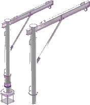
Description
PRELIMINARY DAVIT ARM CALCULATION
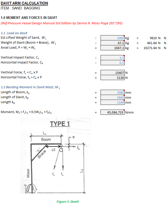
DAVIT ARM CALCULATION
ITEM :SAND BAGGING
1.0 MOMENT AND FORCES IN DAVIT
(Ref:Pressure Vessel Design Manual 3rd Edition by Dennis R. Moss Page 291~295)
1.1 Load on davit
Est Lifted Weight of Sand, WL
Weight of Davit (Boom + Brace), W1
Axial Load, P = WL + W1
Vertical Impact Factor, Cv
Horizontal Impact Factor, Ch
Vertical Force, fv = Cv x P
Horizontal Force, fh = Ch x P
1.2 Bending Moment in Davit Mast, M1
Length of Boom, L1
Length of Davit, L2
Length L5
Moment, M1 = fvL1 + 0.5W1L1 + fhL2
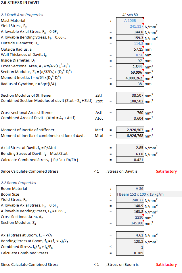
2.0 STRESS IN DAVIT
2.1 Davit Arm Properties
Mast Material
Yield Stress, Fy
Allowable Axial Stress, Fa = 0.6Fy
Allowable Bending Stress, Fb = 0.66Fy
Outside Diameter, Do
Outside Radius, a
Wall Thickness of Davit, tp
Inside Diameter, Di
Cross Sectional Area, A1 = π/4 x(Do2-Di2)
Section Modulus, Z1 = (π/32Do)x (Do4-Di4)
Moment Inertia, I = π/64 x(Do4-Di4)
Radius of Gyration, r = Sqrt(I/A)
Section Modulus of Stiffener
Combined Section Modulus of davit (Ztot = Z1 + Zstf)
Cross sectional Area stiffener
Combined Area of Davit (Atot = A1 + Astf)
Moment of Inertia of stiffener
Moment of Inertia of combined section of davit
Axial Stress at Davit, fa = P/Atot
Bending Stress at Davit, fb = Mtot/Ztot
Calculate Combined Stress, ( fa/Fa + fb/Fb )
Since Calculate Combined Stress
2.2 Boom Properties
Boom Material
Boom Size
Yield Stress, Fy
Allowable Axial Stress, Fa = 0.6Fy
Allowable Bending Stress, Fb = 0.66Fy
Cross Sectional Area, A2
Section Modulus, Z2
Axial Stress at Boom, fa = P/A
Bending Stress at Boom, fb = (fv xL5)/Z2
Combined Stress, fa/Fa + fb/Fb
Calculate Combined Stress
Since Calculate Combined Stress
3.0 WELDED DESIGN JOINT
(Ref:Pressure Vessel Handbook 12th Edition by Eugene F. Megyesy Page 459)
3.1 Davit Arm Bracket
Vertical Shear, V
Bending Moment, M = lV
Horizontal Weld Length,b
Vertical Weld Length,d
Length of Weld, Aw
Fillet Weld Used
Section Modulus (Bending Moment),Sw
Allowable load on weld,f
Vertical Shear Forces,Ws =V/Aw
Bending Forces, Wb = M/Sw
Resultant Force, W =(Wb2 + Ws2)1/2
Fillet Weld Leg Size,w =W/f
Since Calc. weld size> Weld used
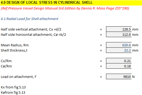
4.0 DESIGN OF LOCAL STRESS IN CYLINDRICAL SHELL
(Ref:Pressure Vessel Design Manual 3rd Edition by Dennis R. Moss Page 255~290)
4.1 Radial Load for Shell attachment
Half side vertical attachment, Cx =d/2
Half side horizontal attachment, Cø =b/2
Mean Radius, Rm
Shell thickness,t
Cx/Rm
Cø/Rm
Load on attachment, F
Kx from fig 5.13
Køfrom fig 5.13
Calculation Reference
Davit Arm Design
Hoisting and Lifting
Crane Design
Calculation Preview

Full download access to any calculation is available to users with a paid or awarded subscription (XLC Pro).
Subscriptions are free to contributors to the site, alternatively they can be purchased.
Click here for information on subscriptions.