Lift Lug calc for Skid
Description
PLEASE NOTE: "Lift Lug calc for Skid" has links with "Weight & Bolting_lse.xls" These may be downloaded separately or together as a zip file.
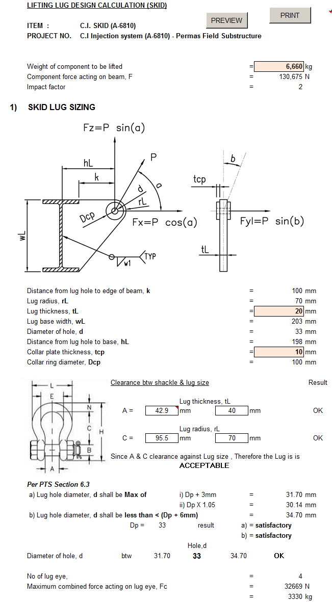
LIFTING LUG DESIGN CALCULATION (SKID)
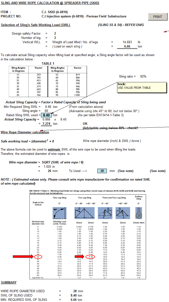
ITEM : C.I. SKID (A-6810)
PROJECT NO. C.I Injection system (A-6810) - Permas Field Substructure
Weight of component to be lifted
Component force acting on beam, F
Impact factor
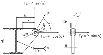
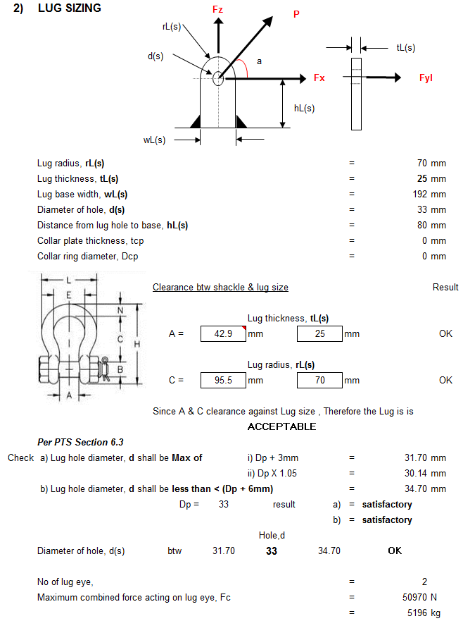
SKID LUG SIZING
Distance from lug hole to edge of beam, k
Lug radius, rL
Lug thickness, tL
Lug base width, wL
Diameter of hole, d
Distance from lug hole to base, hL
Collar plate thickness, tcp
Collar ring diameter, Dcp
Clearance btw shackle & lug size
Lug thickness, tL
A = 42.9 mm 40
Lug radius, rL
C = 95.5 mm 70
Since A & C clearance against Lug size , Therefore the Lug is is
ACCEPTABLE
Per PTS Section 6.3
a) Lug hole diameter, d shall be Max of i) Dp + 3mm
ii) Dp X 1.05
b) Lug hole diameter, d shall be less than < (Dp + 6mm)
Dp = 33 result a)
b)
Hole,d
Diameter of hole, d btw 31.70 33 34.70
No of lug eye,
Maximum combined force acting on lug eye, Fc
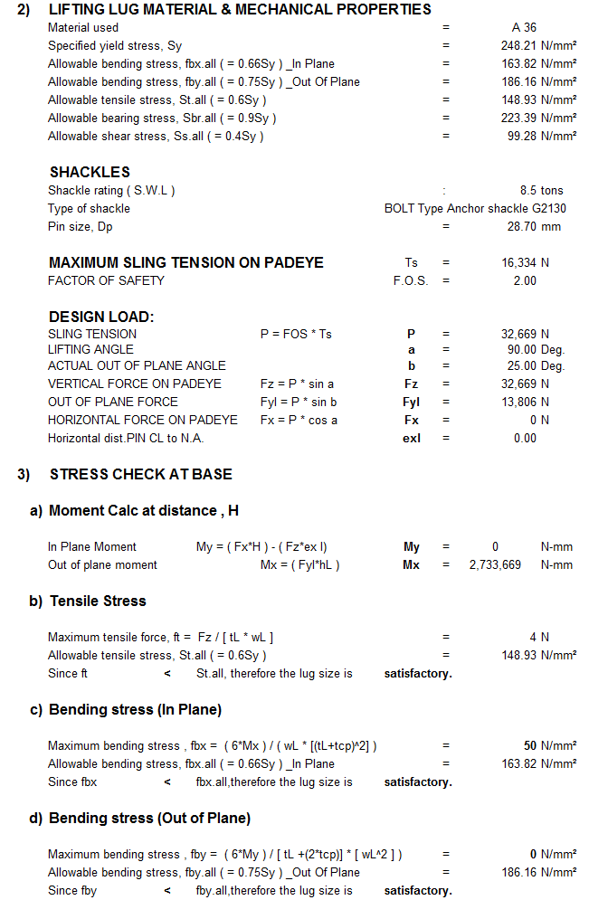
LIFTING LUG MATERIAL & MECHANICAL PROPERTIES
Material used
Specified yield stress, Sy
Allowable bending stress, fbx.all ( = 0.66Sy ) _In Plane
Allowable bending stress, fby.all ( = 0.75Sy ) _Out Of Plane
Allowable tensile stress, St.all ( = 0.6Sy )
Allowable bearing stress, Sbr.all ( = 0.9Sy )
Allowable shear stress, Ss.all ( = 0.4Sy )
SHACKLES
Shackle rating ( S.W.L )
Type of shackle BOLT Type Anchor shackle G2130
Pin size, Dp
MAXIMUM SLING TENSION ON PADEYE Ts
FACTOR OF SAFETY F.O.S.
DESIGN LOAD:
SLING TENSION P = FOS Ts P
LIFTING ANGLE a
ACTUAL OUT OF PLANE ANGLE b
VERTICAL FORCE ON PADEYE Fz = P sin a Fz
OUT OF PLANE FORCE Fyl = P sin b Fyl
HORIZONTAL FORCE ON PADEYE Fx = P cos a Fx
Horizontal dist.PIN CL to N.A. exl
STRESS CHECK AT BASE
Moment Calc at distance , H
In Plane Moment My = ( FxH ) - ( Fzex l) My
Out of plane moment Mx = ( FyIhL ) Mx
Tensile Stress
Maximum tensile force, ft = Fz / [ tL wL ]
Allowable tensile stress, St.all ( = 0.6Sy )
Since ft < St.all, therefore the lug size is satisfactory.
Bending stress (In Plane)
Maximum bending stress , fbx = ( 6Mx ) / ( wL [(tL+tcp)^2] )
Allowable bending stress, fbx.all ( = 0.66Sy ) _In Plane
Since fbx < fbx.all,therefore the lug size is satisfactory.
Bending stress (Out of Plane)
Maximum bending stress , fby = ( 6My ) / [ tL +(2tcp)] [ wL^2 ] )
Allowable bending stress, fby.all ( = 0.75Sy ) _Out Of Plane
Since fby < fby.all,therefore the lug size is satisfactory.
Combined stresses,
U = St/St.all + fby/fby.all + fbx/fbx.all
Since U < 1, therefore the lug size is satisfactory.
SHEAR stress (In Plane)
Maximum SHEAR stress , fsx = Fx / [ wL tL ]
Allowable shear stress, Ss.all ( = 0.4Sy )
Since fsx < Ss.all,therefore the lug size is satisfactory.
Bending stress (Out of Plane)
Maximum SHEAR stress , fsy = Fyl / [ wL tL ]
Allowable shear stress, Ss.all ( = 0.4Sy )
Since fsx < Ss.all,therefore the lug size is satisfactory.
CHECKING VON-MISES CRITERIA
Sum of stress in X-PLANE fx = St + fby
Sum of stress in Y-PLANE fy = St + fbx
Therefore, average Shear stress fxy = SQRT [ (fsx^2)+(fsy^2) ]
Maximum Combined stress
Fcomb = SQRT [ (fx^2)+(fy^2)-(fx+fy+3fxy^2) ]
Allowable combined stress : Fcomb.all ( = 0.66Sy )
Since fsx < Ss.all,therefore the lug size is satisfactory.
STRESS CHECK AT PIN HOLE
Tensile Stress
Maximum tensile force, P
Cross sectional area of lug eye, At = [ 2 ( tL ( rL - d/2 ))] + [ 2 ( tcp (( Dcp/2) - d/2 ))] + [ 2 ( tcp (( Dcp/2) - d/2 ))]
Tensile stress, St
Allowable tensile stress, St.all ( = 0.6Sy )
Since St < St.all, therefore the lug size is satisfactory.
Bearing Stress
Maximum bearing force, P
Cross sectional area of lug eye, Ab = Dp ( tL + 2tcp )
Bearing stress, Sbr = Fbr / Ab
Allowable bearing stress, Sbr.all ( = 0.9Sy )
Since Sbr < Sbr.all,therefore the lug size is satisfactory.
Shear Stress `
Maximum shear force, P
Cross sectional area of lug eye, At = [ 2 ( tL ( rL - d/2 ))] + [ 2 ( tcp (( Dcp/2) - d/2 ))] + [ 2 ( tcp (( Dcp/2) - d/2 ))]
Shear stress, Ss
Allowable shear stress, Ss.all ( = 0.4Sy )
Since Ss < Ss.all,therefore the lug size is satisfactory.
Combined stresses,
U = St/St.all + fby/fby.all + fbx/fbx.all
Since U < 1, therefore the lug size is satisfactory.
WELD SIZE CALCULATIONS
Weld leg used,
Weld throat thickness used, tr
Filler metal material
Fillet weld joint efficiency, E
Welding stress for steel grade 43 ( E-43 ),
Allowable welding stress,Sw
Tensile Stress
Maximum tensile force,Ft
Area of weld, Aw = 2(tL+wL)tr
Tensile stress, St = [(Ft/Aw)]
Since St < Sw,therefore weld leg is satisfactory.
Shear stress
Maximum shear force,Ft
Shear stress, Ss = (Ft/Aw)
Allowable welding stress for steel grade 43 ( E-43 ), Sw
Since Ss < Sw,therefore weld leg dimension is SATISFACTORY.
Bending stress
Maximum bending force,Fb
Bending stress, Sb = [(Fb/Aw)]
Allowable welding stress for steel grade 43 ( E-43 ), Sw
Calculation Reference
Skid Design
Structural Steel Design
Lifting Lug
Calculation Preview
Full download access to any calculation is available to users with a paid or awarded subscription (XLC Pro).
Subscriptions are free to contributors to the site, alternatively they can be purchased.
Click here for information on subscriptions.