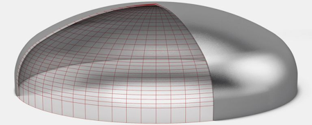
Semi-elliptical head calculator
Description
Program calculates eliptical head wall thickness and max operating pressure,using ASME Sec. 8 Div 1. UG33.
The progam allows to select comon plates material property and operating tempreture.
The shape ratio (Inside crown radius and Inside knuckle radius) calculated as per the code.
Allowed Operating pressure calculate using the wall thickness after forming.
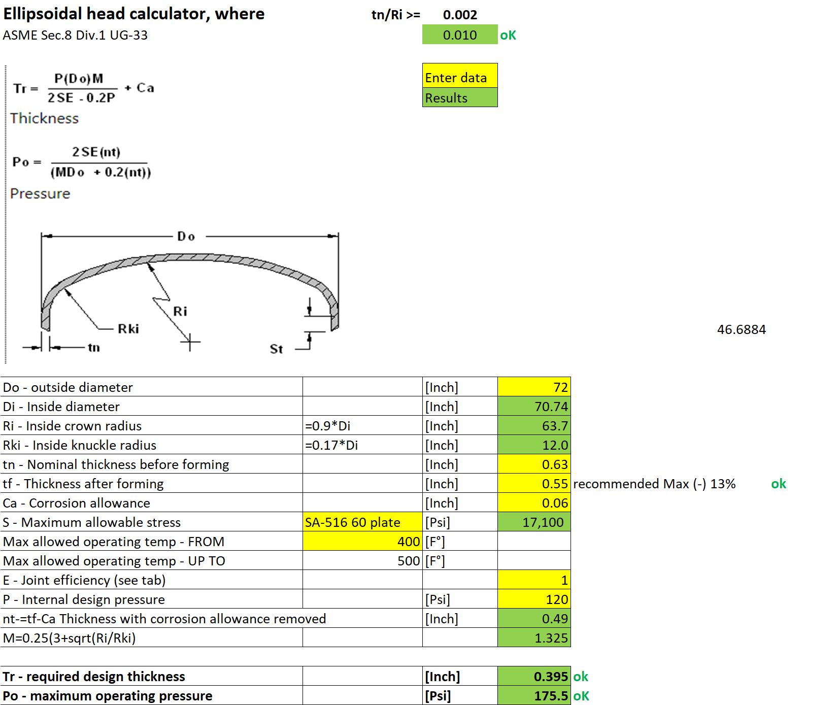
To calculate the elliptical head wall thickness and maximum operating pressure using ASME Sec. 8 Div 1. UG33, we need to follow the guidelines and formulas provided in the code. Here's a step-by-step approach:
-
Material Selection: The user should be able to select common plate materials. Each material will have its own allowable stress values at different temperatures. This data is usually provided in ASME tables.
-
Operating Temperature: The user should input the operating temperature. This will be used to determine the allowable stress for the selected material at that temperature.
-
Shape Ratio Calculation:
- Inside Crown Radius (Ri): This is typically half the inside diameter of the head.
- Inside Knuckle Radius (ri): This is calculated as per the code. For a 2:1 elliptical head, the knuckle radius is typically 0.17 times the inside diameter.
-
Wall Thickness Calculation:
- The minimum required thickness of the head after forming can be calculated using the formula provided in UG-33. This will consider factors like internal pressure, inside crown radius, and allowable stress.
-
Maximum Operating Pressure Calculation:
- Using the calculated wall thickness after forming, the maximum allowable operating pressure can be determined. This will also consider the joint efficiency and other factors as per the code.
- Using the calculated wall thickness after forming, the maximum allowable operating pressure can be determined. This will also consider the joint efficiency and other factors as per the code.
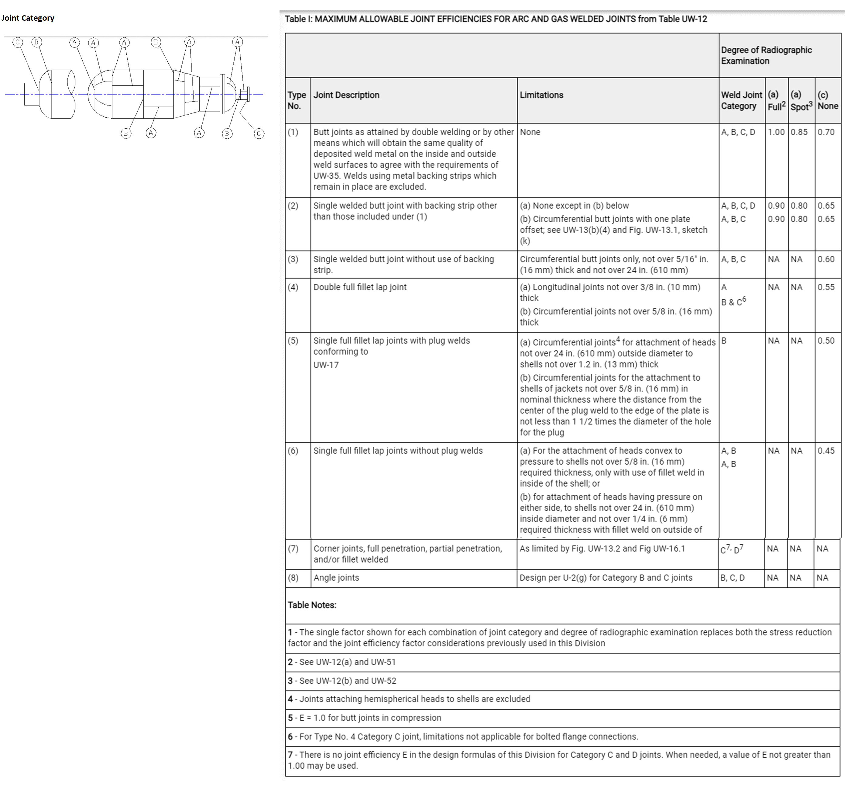
In the context of the ASME Boiler and Pressure Vessel Code (BPVC), a 'joint category' refers to the classification of welded joints based on their location and function in a pressure vessel or boiler. The joint category is used to determine the type of inspection and the extent of radiographic examination required for the welded joint.
The ASME BPVC Section VIII (which deals with the design and fabrication of pressure vessels) defines several joint categories:
-
Category A: Longitudinal or spiral joints in shells, drums, or headers of boilers, pressure vessels, and heat exchangers. This category also includes joints between different sections of a vessel, such as between a shell and a head.
-
Category B: Circumferential joints in shells, drums, or headers of boilers, pressure vessels, and heat exchangers.
-
Category C: Joints connecting tubes, pipes, or tubesheets in boilers, pressure vessels, and heat exchangers.
-
Category D: Joints in nozzles, communicating chambers, or manholes (excluding flanged connections) that are attached to shells, drums, headers, or other nozzles, communicating chambers, or manholes.
-
Category E: Joints in tubes, pipes, or fittings that are not covered by Categories A, B, C, or D.
-
Category F: All joints in attachments (e.g., lugs, clips, brackets) that are welded directly to the pressure boundary.
Each joint category has specific requirements for radiographic examination, and the extent of the examination is determined by the joint efficiency factor. The joint efficiency factor, in turn, affects the allowable stress calculations for the pressure vessel.
Calculation Preview
Full download access to any calculation is available to users with a paid or awarded subscription (XLC Pro).
Subscriptions are free to contributors to the site, alternatively they can be purchased.
Click here for information on subscriptions.