PRECAST STRUCTURAL DESIGN

Description
This spreadsheet is a design of all precast members. It is amazingly helpful for structural designers.
- Project Description
The building is a 12-storey office block in a mix commercial development comprising carparks,
shopping malls and service apartments.A typical floor of the building measuring 24 m x 72 m with 8 m building grids in both directions is shown in Figure 4.1. The design floor-to-floor height is 3.6 m. Staircases, lift cores and other building services such as toilets, AHU, M&E risers are located at each end of the floor
which are to be cast in-situ.
- Design Information
a. Codes of Practice
BS 6399 Design Loading for Building
CP 65 The Structural Use of Concrete
CP3, Chapter V Wind Load
b. Materials
Concrete
C30 for topping, walls and all other in-situ works
C45 for precast beam
C50 for precast columns and hollow core slabs
Steel
fy = 250 N/mm² mild steel reinforcement
fy = 460 N/mm² high yield steel reinforcement
fy = 485 N/mm² high yield steel reinforcement
c.Dead loads
Concrete density
Partitions, finishes and services
Brickwalls
d.Liveloads
Offices, staircases, corridors
Lift lobby, AHU rooms
Toilet
- Structural System
Precast construction is adopted from the second storey upwards to take advantage of the regular building grids and simple structural layout. The areas from grids A to C and from J to K are, however, cast in-situ due to drops, floor openings and water-tightness considerations. Beside acting as load bearing walls, staircase wells and lift cores also function as stabilising cores for the superstructure. The walls are 300 mm thick, cast in-situ and are tied monolithically at every floor. The precast components consist of hollow core slabs, beams, columns and staircase flights.
a. Hollow core slabs
The design of hollow core slabs (215 mm thick) is based on class 2 prestressed concrete structure with minimum 2 hours fire rating. The hollow core slabs are cast with C50 concrete. Each unit (1.2 m nominal width) is designed as simply supported with nominal 100 mm seat at the support. Resultant stresses are checked at serviceability and at prestress transfer. Design of the slab is carried out by the specialist supplier.
b. Precast beams
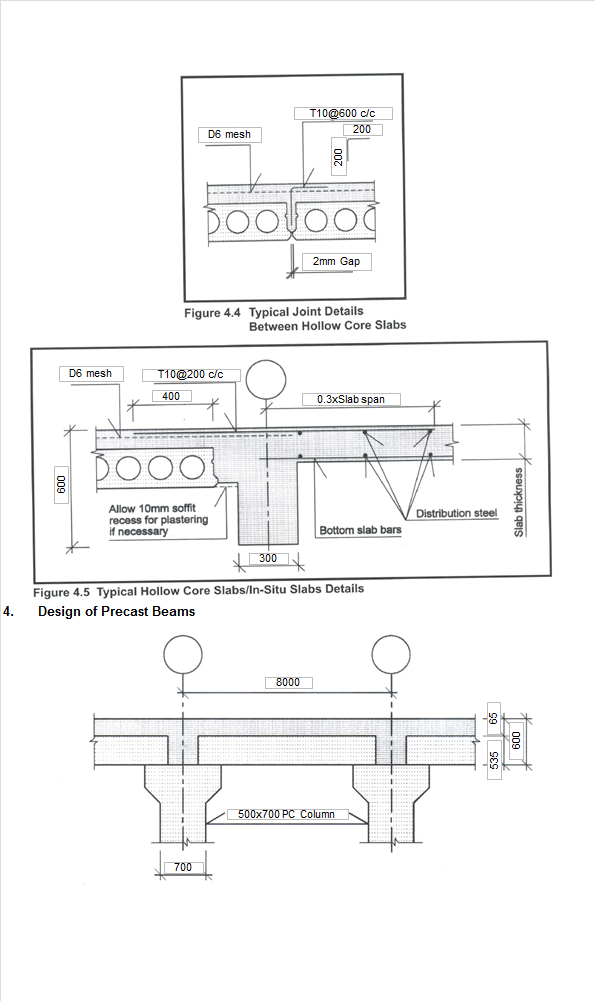
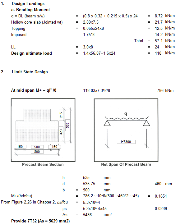
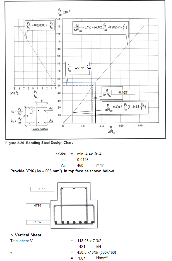
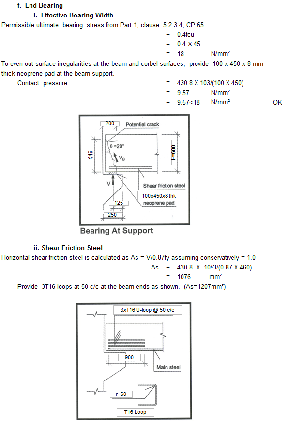
535 mm deep full precast beams are used in the office area. The beams, which are unpropped during construction, are seated directly onto column corbels and are designed as simply supported structures at the final stage. To limit cracking of the topping concrete at the supports, site placed reinforcement is provided as shown in the typical details in Figure 4.2.
c. Precast columns
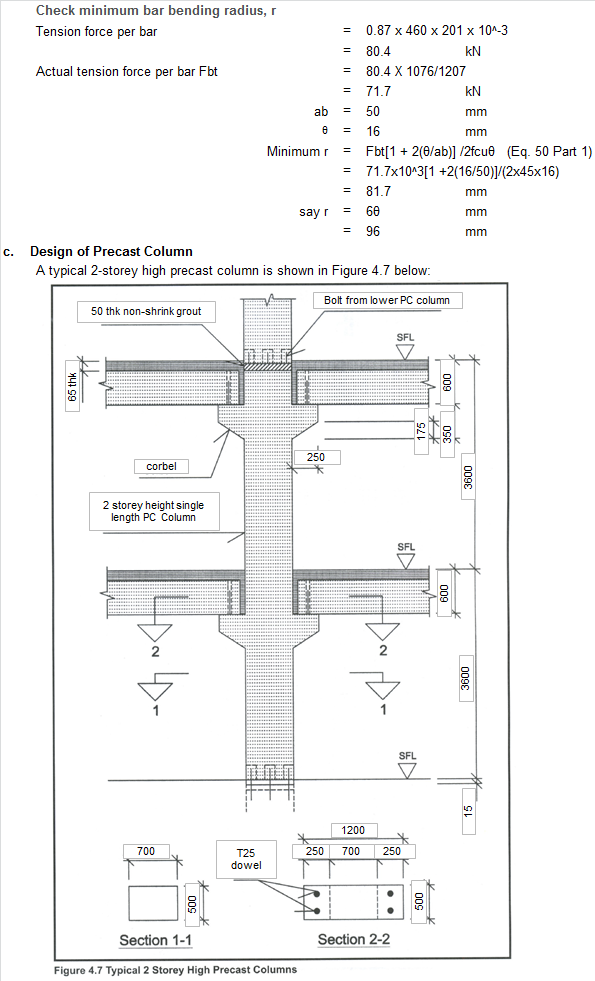
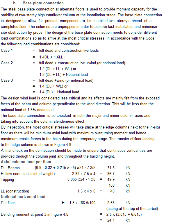
The columns are 500 mm x 700 mm and are cast 2-storey in height with base plate connection at every alternate floor. They are designed as pin-ended at the ultimate limit state. The base plate connection is designed with moment capacity to enable the columns to behave as a 2-storey high cantilever. This is to facilitate floor installation works which are to be carried out two floors in advance of a finally tied floor at any one time during the construction of the office block. The use of base plate connection will eliminate heavy column props and result in a safer and neater construction site. A nominal 50 mm gap is detailed in the design of the column-to-column connection in order to provide sufficient tolerances for the insertion of in-situ reinforcement at the beam support regions. The gap will be filled with C50 non-shrink grout. Each column is cast with reinforced concrete corbels in the direction of the precast beams. The corbels are provided with T25 dowel bars which are used to prevent toppling of the precast beams when the hollow core slabs are laid. The depth of the corbel is designed to be concealed visually within the final ceiling space. At the final state, all columns are considered braced in both directions.
d. Floor diaphragm action and structural integrity
All precast components are bound by a 65 mm thick concrete topping which is reinforced with a layer of steel fabric. The steel fabric serves as structural floor ties in order to satisfy the integrity ties requirement under the building robustness design considerations. The final floor structure will behave as a rigid diaphragm which transmits horizontal loads to the stabilising cores at each end of the floor.
- Design of Precast Components
a. Design of Hollow Core Slab
Calculation Reference
Precast Structural Design
BS 6399
CP3
Calculation Preview
Full download access to any calculation is available to users with a paid or awarded subscription (XLC Pro).
Subscriptions are free to contributors to the site, alternatively they can be purchased.
Click here for information on subscriptions.