Pin and Lug - Static and Fatigue.xls
Description
Calculating the fatigue strength of a lug involves understanding the cyclic loading conditions and material properties to ensure the lug can withstand repetitive loading without failure. Here's a step-by-step process to calculate the fatigue strength of a lug:
-
Identify the loading conditions: Determine the cyclic loading conditions the lug is subjected to, such as the minimum and maximum loads, the load range, and the number of cycles.
-
Determine the lug geometry: Define the lug's dimensions, such as hole diameter (d), edge distance (e), lug thickness (t), and any other relevant geometrical features like fillet radii or notches.
-
Calculate stress concentration factors (SCFs): Identify stress concentrators in the lug, such as holes or fillets, and calculate the SCFs using analytical methods, empirical formulas, or numerical simulations (e.g., finite element analysis).
-
Compute stress ranges: Based on the loading conditions and the lug geometry, calculate the stress ranges acting on the lug, considering both axial and shear stress components. Incorporate the SCFs to account for stress concentrators.
-
Determine the material's S-N curve: Obtain the S-N curve (stress vs. number of cycles) for the lug material, which typically represents the fatigue behavior of the material. This curve can be found in material handbooks or obtained through fatigue testing of the material.
-
Estimate the fatigue life: Using the S-N curve, determine the fatigue life (N) of the lug material for the calculated stress range. The fatigue life is the number of cycles that the material can withstand before failure.
-
Compare the fatigue life to the number of cycles: Compare the estimated fatigue life (N) to the actual number of cycles the lug is expected to experience during its service life. If the fatigue life is less than the number of cycles, the lug may be at risk of failure due to fatigue, and modifications may be required, such as changing the material, redesigning the lug, or reducing the stress concentrations.
-
Factor of safety: Include an appropriate factor of safety to account for uncertainties in the fatigue analysis, such as material variability, manufacturing defects, or loading variations.
In summary, calculating the fatigue strength of a lug involves identifying the loading conditions, determining the lug geometry, calculating stress concentration factors, computing stress ranges, determining the material's S-N curve, estimating the fatigue life, and comparing it to the number of cycles the lug is expected to experience. Proper evaluation of the lug's fatigue strength is crucial to ensuring its long-term performance and preventing premature failure due to fatigue.
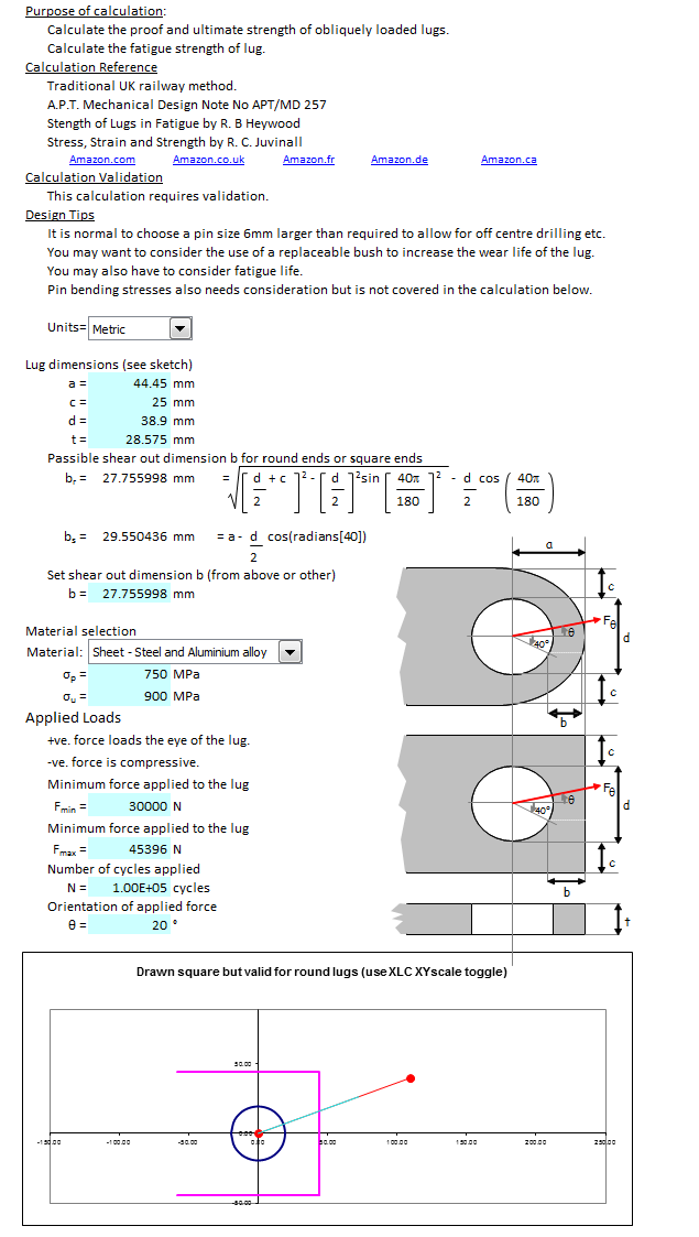
Purpose of calculation:
Calculate the proof and ultimate strength of obliquely loaded lugs.
Calculate the fatigue strength of lug.
This is an extension of a simpler calculation which only considers static strength.
Calculation Reference
Traditional UK railway method.
A.P.T. Mechanical Design Note No APT/MD 257
Strength of Lugs in Fatigue by R. B Heywood
Stress, Strain and Strength by R. C. Juvinall
Calculation Validation
This calculation requires validation.
Design Tips
It is normal to choose a pin size 6mm larger than required to allow for off centre drilling etc.
You may want to consider the use of a replaceable bush to increase the wear life of the lug.
You may also have to consider fatigue life.
Pin bending stresses also needs consideration but is not covered in the calculation below.
Design Procedure
================
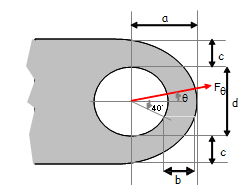
Lug Dimensions
Material selection
Applied Loads
+ve. force loads the eye of the lug.
-ve. force is compressive.
Minimum force applied to the lug
Minimum force applied to the lug
Number of cycles applied
Orientation of applied force
Summary
Proof strength check.
Ultimate strength check.
Fatigue strength check.
Static Strength Design of Lugs
==============================
1 Calculate Lug Proof Strength when θ=0
Tensile Proof Strength
Shear Proof Strength
Check shear stress at ¸=90°
Pull out strength - check shear stress at θ=40°
Check limiting shear stress
Proof Bearing Strength
Limiting lug proof strength
2) Calculate Lug Ultimate Strength when θ=0
Tensile ultimate Strength
Shear ultimate Strength
Check shear stress at θ=90°
Pull out strength - check shear stress at θ=40°
Check limiting shear stress
Note - Bearing strength is not considered for an ultimate strength case.
Limiting lug ultimate strength
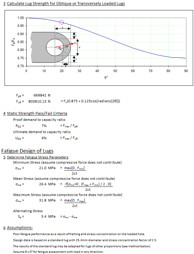
3) Calculate Lug Strength for Oblique or Transversely Loaded Lugs
4) Static Strength Pass/Fail Criteria
Proof demand to capacity ratio
Ultimate demand to capacity ratio
Fatigue Design of Lugs
======================
5) Determine Fatigue Stress Parameters
Minimum Stress (assume compressive force does not contribute)
Mean Stress (assume compressive force does not contribute)
Maximum Stress (assume compressive force does not contribute)
Alternating Stress
6) Assumptions:
Poor fatigue performance as a result of fretting and stress concentration on the loaded hole.
Design data is based on a standard lug with 25.4mm diameter and stress concentration factor of 2.5.
The results of the standard lug may be adapted for lugs of other proportions (see method below).
Assume ? = 0° for fatigue assessment with load in any direction.
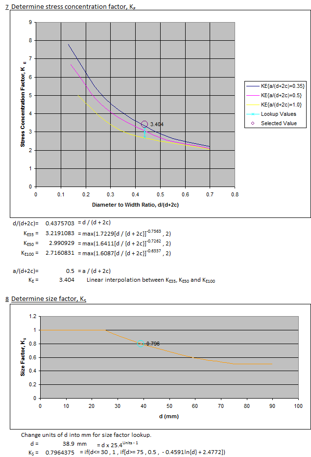
7) Determine stress concentration factor, KE
8) Determine size factor, KS
Change units of d into mm for size factor lookup.
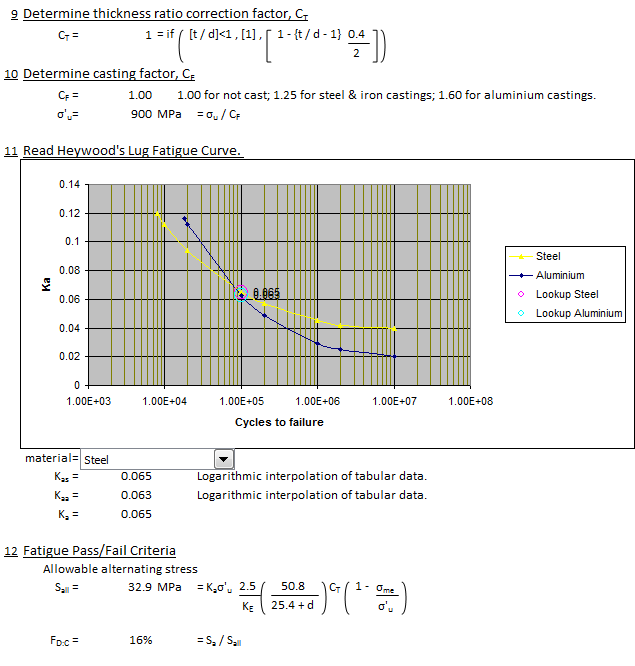
9) Determine thickness ratio correction factor, CT
10) Determine casting factor, CF
11) Read Heywood's Lug Fatigue Curve.
12) Fatigue Pass/Fail Criteria
Allowable alternating stress
Calculation Reference
Machine Design
Bruhn Design of aircraft
Heywood Design of Lugs
Calculation Preview

Full download access to any calculation is available to users with a paid or awarded subscription (XLC Pro).
Subscriptions are free to contributors to the site, alternatively they can be purchased.
Click here for information on subscriptions.