
AXIAL AND LATERAL LOAD PILES (FEM)
 (4/117)
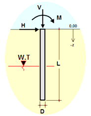
Description
Axially and Laterally Loaded Bored Pile by Finite Elements (Single Soil Layer)
Analyses a single reinforced concrete bored pile in one soil layer under axial load, horizontal load and moment, for example a cantilever pile retaining an excavation. The pile is modelled as beam elements on Winkler soil springs, and the workbook also estimates lateral and axial capacity and designs the pile reinforcement.
Method
- Finite element beam on elastic springs; the subgrade modulus can be constant, linear or parabolic with depth. Results are plotted as moment, shear, soil pressure, axial force, horizontal and vertical deflection, and slope diagrams
- Loads from active earth pressure and surcharge on the exposed (retained) height, plus extra loads at the pile head
- Lateral capacity from Broms-type expressions for the cohesive and frictional parts using the relative stiffness length T = (EI/k)1/5; head displacement limit of pile length/1000
- Axial capacity as base resistance plus shaft friction with separate factors of safety, and pullout capacity
- Shear check with Vc = 0.166√f′c on the core area; longitudinal steel from a mechanical reinforcement ratio interaction chart; stirrup size and spacing; material quantities
Inputs
Soil properties and water table; pile diameter, embedded length and exposed height; concrete and steel grades; surcharge and head loads; bar and stirrup choices.
The stored example, a 65 cm pile embedded 6 m in soil with c′ = 20 kN/m² and φ = 30° retaining 5 m, gives a maximum horizontal force of 77.9 kN, maximum moment of 194.5 kNm, head displacement of 4.4 mm (limit 6 mm) and an allowable axial load of 373 kN. SI units.
Please note
- The frictional lateral capacity 0.5γDKpT³ is not divided by a length as in Broms’ expression, so it has the units of a moment and appears to overstate the capacity.
- The stirrups are sized for the average of Vc and Vu; in the example the sheet reports “Inadequate Reinforcement”.
- Sheets are protected. No macros.
Author: Turan Babacan. References: Geotechnics; Soil Mechanics; The Finite Element Method; Design of Piles; Reinforced Concrete Design.
Calculation Preview


 (4/117)
Full download access to any calculation is available to users with a paid or awarded subscription (XLC Pro).
Subscriptions are free to contributors to the site, alternatively they can be purchased.
Click here for information on subscriptions.





Thank you for your axially and laterally loaded pile calculation. We checked the axial capacity in your example (Qb = 751.7 kN, Qs = 367.6 kN, allowable 373.1 kN) and the concrete shear capacity, and both agree with the sheet.
While rewriting the description we found one error. Cell EB10 calculates the frictional lateral capacity as 0.5·γ·D·Kp·T³. Broms' short-pile expression is 0.5γDL³Kp/(e + L); without the division by (e + L) the result has the units of a moment (kN·m) rather than a force, so Hu (180.9 kN in the example) and the moment capacity in EB18 built from it are overstated.
You may also want to consider the stirrup design in HN17, which sizes the stirrups for the average of Vc and Vu; that is unusual, and the example reports "Inadequate Reinforcement".
We have mentioned these points in the file's description so users are aware. If you upload a corrected version, we will review it and publish it as the next version.
ExcelCalcs Review Team