
MONORAIL.xls
 (4/43)
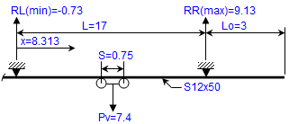
Description
Underhung Monorail Beam Check for S and W Shapes (AISC ASD and CMAA 74)
Checks an underhung monorail beam, an S-shape or a W-shape on separate sheets, analysed as a simple span with or without an overhang. It covers strong- and weak-axis bending, lateral flange bending from torsion, deflection, and local bending of the bottom flange under the trolley wheels by two methods.
Method
- Vertical load Pv = P(1 + impact) + trolley + hoist; horizontal load as a percentage of P. Self-weight of the beam is included.
- Moments with the wheel pairs placed for maximum effect; reactions with the overhang loaded
- Allowable stresses to AISC 9th Edition ASD (Fbx = 12000Cb/(Lbd/Af) ≤ 0.60Fy, Fby = 0.75Fy), with warping stress from torsion added to the weak-axis stress
- Deflection limits L/450 (span) and Lo/450 (overhang), from CMAA 74
- Bottom flange bending by a simple effective-width method and by the CMAA 74 coefficient method, combined with the beam stresses and checked against 0.66Fy
Inputs
- Beam size (from the built-in database), Fy, span, overhang, unbraced lengths and Cb values
- Lifted load, trolley and hoist weights, impact and horizontal load factors, number and spacing of wheels, wheel position on the flange
Outputs
Reactions, moments, stresses and stress ratios for the span and the overhang, deflections, and flange bending stresses, each with an O.K. check.
The stored example, an S12x50 spanning 17 ft with a 3 ft overhang and a 6 kip lifted load, gives a span stress ratio of 0.66, a span deflection of L/1445 and a peak combined flange stress of 21.6 ksi at the flange tip against 23.76 ksi.
Please note
- The overhang’s unbraced length Lbo is user-chosen (the documentation lists the differing recommendations).
- Longitudinal (traction) forces are ignored. US customary units; AISC 9th Edition ASD has been superseded. Sheets protected without a password, formulas hidden. No macros.
- Written by Alex Tomanovich, P.E. References include AISC 9th Edition ASD, CMAA Specification No. 74 (2004), ANSI MH27.1 and the USS Steel Design Manual.
Calculation Preview


 (4/43)
Full download access to any calculation is available to users with a paid or awarded subscription (XLC Pro).
Subscriptions are free to contributors to the site, alternatively they can be purchased.
Click here for information on subscriptions.
Comments: 16
×

11 months ago
Could you please modify the sheet to use SI units?

5 years ago
can any one send it to me cause it is a big need and i cant afford the subscription

6 years ago
There is only an option for 2 or 4 wheels. 8 has not been considered.

6 years ago
How do you input total number of wheel equals 8?

12 years ago
Mr.ATomanovich , How fatigue design to be carried out for mono rail ? Is it possible to include in your spreadsheet.

12 years ago
It was brought to my attention that in both the "S-shaped Monorail Beam" and "W-shaped Monorail Beam" worksheets that there was an error which would result in being overly conservative for only the typically rare case where the spacing (S) between 2-pairs of wheels of the trolley is equal to or exceeds the value of (2-SQRT(2))*L = 0.586*L.
When the wheel spacing for 2-pairs of wheels is < 0.586*L the maximum moment is determined by M(max) = P*(L-S/2)^2/(2*L), and when the wheel spacing for 2-pairs of wheels is >= 0.586*L, the maximum moment is determined by M(max) = P*L/4. The preceding, of course, excludes the monorail beam self weight.
I did have the correct programming logic to differentiate between these 2 conditions for calculating the maximum moment. However, for the case where S >= 0.586*L, I inadvertently forgot to divide the value of "Pv" by 2 (where "Pv" represents the total of the lifted load + trolley weight + hoist weight), since 1-pair of wheels is actually off of the beam span and not considered for the purpose of analysis.
Thus, this error would result in an overly conservative maximum moment, by a factor of 2, for trolleys with 2-pairs of wheels. The fast majority of maintenance/service type monorails have wheel spacings which are normally far less than the 0.586*L value. However, while rare in occurrence or not, the corrections needed to be made to correctly address any situation.
When the wheel spacing for 2-pairs of wheels is < 0.586*L the maximum moment is determined by M(max) = P*(L-S/2)^2/(2*L), and when the wheel spacing for 2-pairs of wheels is >= 0.586*L, the maximum moment is determined by M(max) = P*L/4. The preceding, of course, excludes the monorail beam self weight.
I did have the correct programming logic to differentiate between these 2 conditions for calculating the maximum moment. However, for the case where S >= 0.586*L, I inadvertently forgot to divide the value of "Pv" by 2 (where "Pv" represents the total of the lifted load + trolley weight + hoist weight), since 1-pair of wheels is actually off of the beam span and not considered for the purpose of analysis.
Thus, this error would result in an overly conservative maximum moment, by a factor of 2, for trolleys with 2-pairs of wheels. The fast majority of maintenance/service type monorails have wheel spacings which are normally far less than the 0.586*L value. However, while rare in occurrence or not, the corrections needed to be made to correctly address any situation.

13 years ago
Thanks!
15 years ago
It was brought to my attention in both the "S-shaped Monorail Beam" and the 'W-shaped Monorail Beam" worksheets that for the lateral flange bending moment from torsion for the overhang (cantilever) portion, the program calculation cell (cell O69) was incorrectly using the simple span length, "L", when it obviously should have been using the overhang (cantilever) length, "Lo". The text display of the formula was correct in showing "Lo", but again it was the calculation cell that had the error.
With this error of using "L" instead of "Lo", the result from the calculation would have been conservative, but not nearly as much as one might expect. That is due to the fact that the formula used includes a hyperbolic function in the expression.....TANH(Lo*12/at).....where at = SQRT(E*Cw/(J*G)). When the value of (Lo*12/at) is >= say 3.0, the TANH of that approaches 1.0. Thus, the larger the overhang (cantilever) length was, the smaller the conservative error became. Plus, the error that was involved was a good bit less when using the more common "S" shapes as opposed to using "W" shapes for the monorail beam.
I have made the corrections and the new version of this workbook is now version 2.0.
With this error of using "L" instead of "Lo", the result from the calculation would have been conservative, but not nearly as much as one might expect. That is due to the fact that the formula used includes a hyperbolic function in the expression.....TANH(Lo*12/at).....where at = SQRT(E*Cw/(J*G)). When the value of (Lo*12/at) is >= say 3.0, the TANH of that approaches 1.0. Thus, the larger the overhang (cantilever) length was, the smaller the conservative error became. Plus, the error that was involved was a good bit less when using the more common "S" shapes as opposed to using "W" shapes for the monorail beam.
I have made the corrections and the new version of this workbook is now version 2.0.
17 years ago
I made some revisions in the two calculation worksheets of the "MONORAIL.xls" workbook which eliminated some unnecessary conservatism in the analysis as noted below.
At the bottom of the 2nd page of the calculations where bottom flange bending is checked via a simplified approach, the worksheets were originally taking the wheel load to be at the edge of the flange, which was conservative. Now the moment arm for bending has been reduced by subtracting the input distance "a" from the edge of the flange to the center of wheel.
In the 3rd page of the calculations where bottom flange bending is analyzed per CMAA Specification No. 74, the worksheets were using the originally computed bending stress values of "fbx" and "fby" (taken to the extreme outer edges) in the biaxial stress formulas for the analyzed point locations 0, 1, and 2. Again these values were in some cases conservative, depending on the point which was being investigated. Now the bending stress values "fbx" and "fby" are determined at the specific point under consideration (fbxo, fbx1, fbx2 and fbyo, fby1, fby2).
At the bottom of the 2nd page of the calculations where bottom flange bending is checked via a simplified approach, the worksheets were originally taking the wheel load to be at the edge of the flange, which was conservative. Now the moment arm for bending has been reduced by subtracting the input distance "a" from the edge of the flange to the center of wheel.
In the 3rd page of the calculations where bottom flange bending is analyzed per CMAA Specification No. 74, the worksheets were using the originally computed bending stress values of "fbx" and "fby" (taken to the extreme outer edges) in the biaxial stress formulas for the analyzed point locations 0, 1, and 2. Again these values were in some cases conservative, depending on the point which was being investigated. Now the bending stress values "fbx" and "fby" are determined at the specific point under consideration (fbxo, fbx1, fbx2 and fbyo, fby1, fby2).
17 years ago
A few incorrect cell references were brought to my attention in the "MONORAIL.xls" workbook.
Off of the main calculation page to the right for the Y-axis stress ratio, the cell references in cells BB90, BB13, and BE13 were not using "fby(total)", only "fby", and thus were neglecting the stress contribution from torsion, "fwns".
Fortunately the logic statement in cell I90 on the 2nd page of the actual calculations was correct, in that it was using "fby(total)" in the calculation of the stress ratio, so the actual displayed and printed calculations were fine.
This problem occurred in both worksheets of the workbook, and I have made the corrections. The workbook is now version 1.8.
Off of the main calculation page to the right for the Y-axis stress ratio, the cell references in cells BB90, BB13, and BE13 were not using "fby(total)", only "fby", and thus were neglecting the stress contribution from torsion, "fwns".
Fortunately the logic statement in cell I90 on the 2nd page of the actual calculations was correct, in that it was using "fby(total)" in the calculation of the stress ratio, so the actual displayed and printed calculations were fine.
This problem occurred in both worksheets of the workbook, and I have made the corrections. The workbook is now version 1.8.
17 years ago
A potential "quirk" was found in the "MONORAIL.xls" workbook. From Table 6 (Values of Cb) on page 5-121 of the AISC 9th Edition Manual, the minimum value of the bending coefficient (Cb) is 1.0. A value of 1.0 for Cb is what is used most of the time in design, even if conservative. However, if for the cantilever portion of the monorail beam the user chooses to use the Lbo and Cbo values as determined off of the calculation page to the right per the AISC Journal Article by N.S. Tanner, then the calculated value of Cbo can be < 1.0. (The subscript "o" refers to the overhang or cantilever portion of the monorail beam.)
Specifically for the situation of a member with Lbo <= Lu and with an input value of Cbo < 1.0, the two worksheets were ignoring an input value of Cbo < 1.0, treating Cbo as if it were = 1.0, and thus deferring to Fb = 0.6*Fy. This problem involving the use of a Cbo value < 1.0 did not occur for Lbo > Lu.
Again, this potential problem would have only arisen if a value of Cbo < 1.0 was used from the Tanner article in conjunction with Lbo <= Lu.
The corrections have been made, and the updated workbook is now version 1.7.
Alex Tomanovich, P.E.
Specifically for the situation of a member with Lbo <= Lu and with an input value of Cbo < 1.0, the two worksheets were ignoring an input value of Cbo < 1.0, treating Cbo as if it were = 1.0, and thus deferring to Fb = 0.6*Fy. This problem involving the use of a Cbo value < 1.0 did not occur for Lbo > Lu.
Again, this potential problem would have only arisen if a value of Cbo < 1.0 was used from the Tanner article in conjunction with Lbo <= Lu.
The corrections have been made, and the updated workbook is now version 1.7.
Alex Tomanovich, P.E.
18 years ago
A couple of typo errors were pointed out to me recently in the "MONORAIL.xls" workbook.
In the text display of the formula for the x-axis simple span moment (Mx) for a concentrated load at midspan, the text had both divide and multiply symbols between the variables "Pv" and "L/4". The divide symbol should not have been there. In the resultant biaxial stress at point 1 calculation, the text display of the formula for the z-axis stress showed sigma(y), when it should have been sigma(z). These typo errors occurred in both of the calculation worksheets, and they have been corrected in version 1.6.
In the text display of the formula for the x-axis simple span moment (Mx) for a concentrated load at midspan, the text had both divide and multiply symbols between the variables "Pv" and "L/4". The divide symbol should not have been there. In the resultant biaxial stress at point 1 calculation, the text display of the formula for the z-axis stress showed sigma(y), when it should have been sigma(z). These typo errors occurred in both of the calculation worksheets, and they have been corrected in version 1.6.

18 years ago
First off, THANK YOU for sharing the excellent work on all of your spreadsheets; you truly epitomise
18 years ago
In the "MONORAIL.xls" workbook, in both worksheets there was a common "typo-error" discovered. The text version display of AISC 9th Edition Equation F1-8 for allowable x-axis bending stress had the denominator show as "(Lb*12/(d/Af))" where the "/" symbol should have been a " * " symbol to read as "(Lb*12*(d/Af))". The actual calculation cell formulas were correct in all cases. Again, these were "cosmetic" errors only, but they needed to be corrected. This workbook is now version 1.5.
18 years ago
In the "MONORAIL.xls" spreadsheet workbook in both calculation worksheets it was discovered that for the specific case of 2-pairs of wheels (4 wheels
total) I had inadvertently omitted the self weight of the monorail beam in the actual calculation of the strong axis bending moment, Mx. The monorail beam self weight was included in the actual moment calculation for the case of 1-pair of wheels (2 wheels total). The text displaying the formulas used for the moment were correctly shown for both cases, it was the calculation cell for that one case that was in error.
I'm somewhat puzzled at the nature of this error and how it happened, as I usually write out the logic/formula, copy that to the calculation cell, and then substitute the appropriate cell references for each of the variables in the logic/formula. I obviously must have gotten carried away with use of the backspace key during the editing process. It is updated to version 1.4.
Alex Tomanovich, P.E.
Senior Structural Engineer
total) I had inadvertently omitted the self weight of the monorail beam in the actual calculation of the strong axis bending moment, Mx. The monorail beam self weight was included in the actual moment calculation for the case of 1-pair of wheels (2 wheels total). The text displaying the formulas used for the moment were correctly shown for both cases, it was the calculation cell for that one case that was in error.
I'm somewhat puzzled at the nature of this error and how it happened, as I usually write out the logic/formula, copy that to the calculation cell, and then substitute the appropriate cell references for each of the variables in the logic/formula. I obviously must have gotten carried away with use of the backspace key during the editing process. It is updated to version 1.4.
Alex Tomanovich, P.E.
Senior Structural Engineer
Alex