ExcelFEM_3D (for Excel 2007 & Excel 2010)
Description
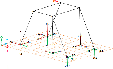
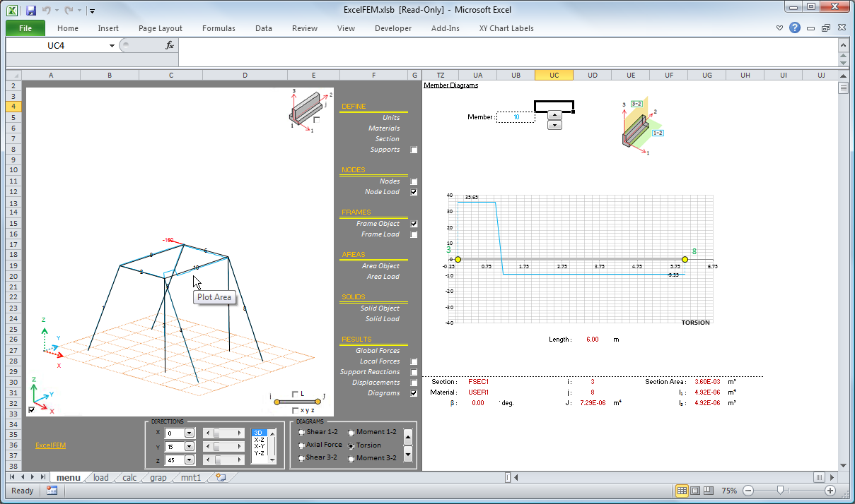
Static structural analysis of 3D linear elastic frames and trusses. Computes the static deflections, reactions, internal element forces using direct stiffness methods. Simply follow the 12 step process.
An older version of this document works with Excel 2003 but is not being further developed
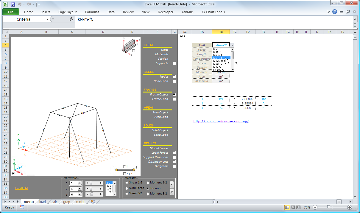
- Define Units
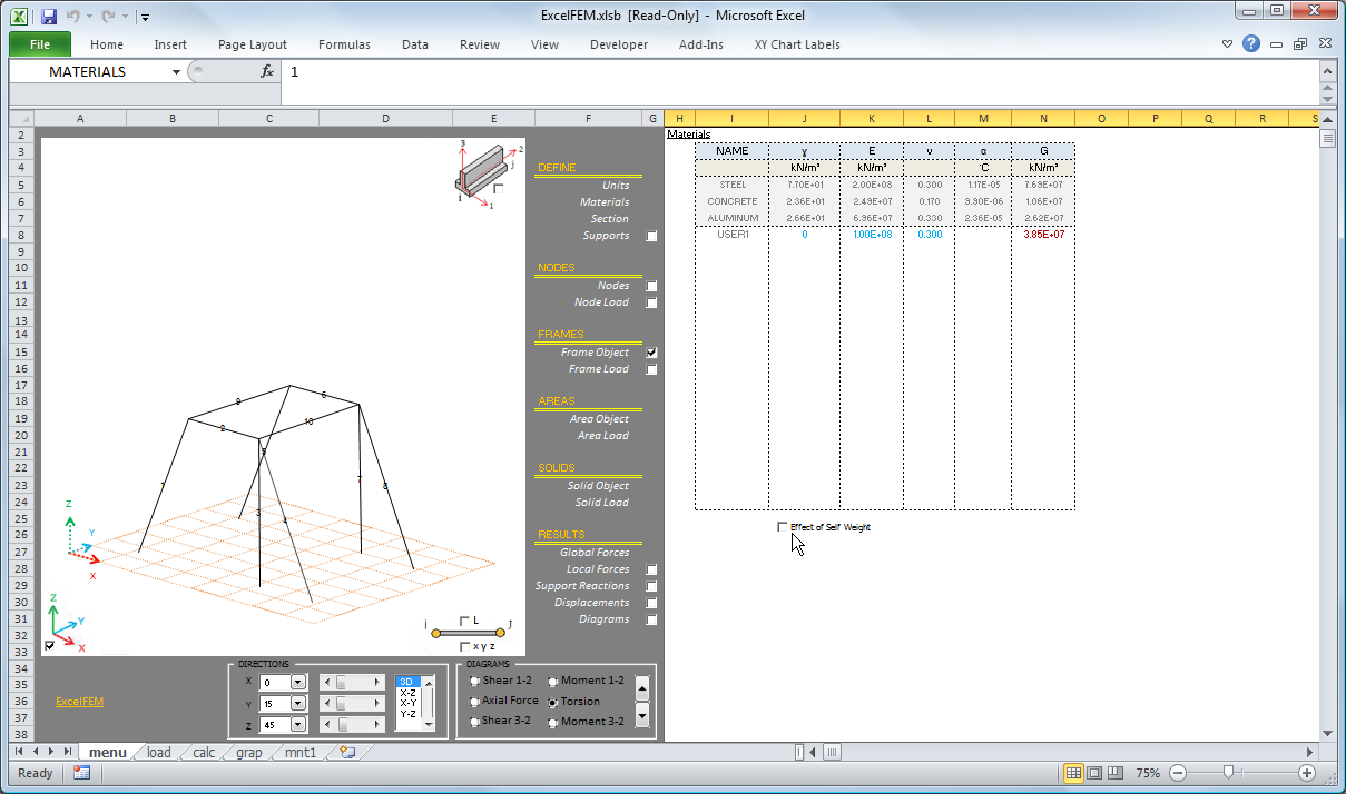
2) Define Materials
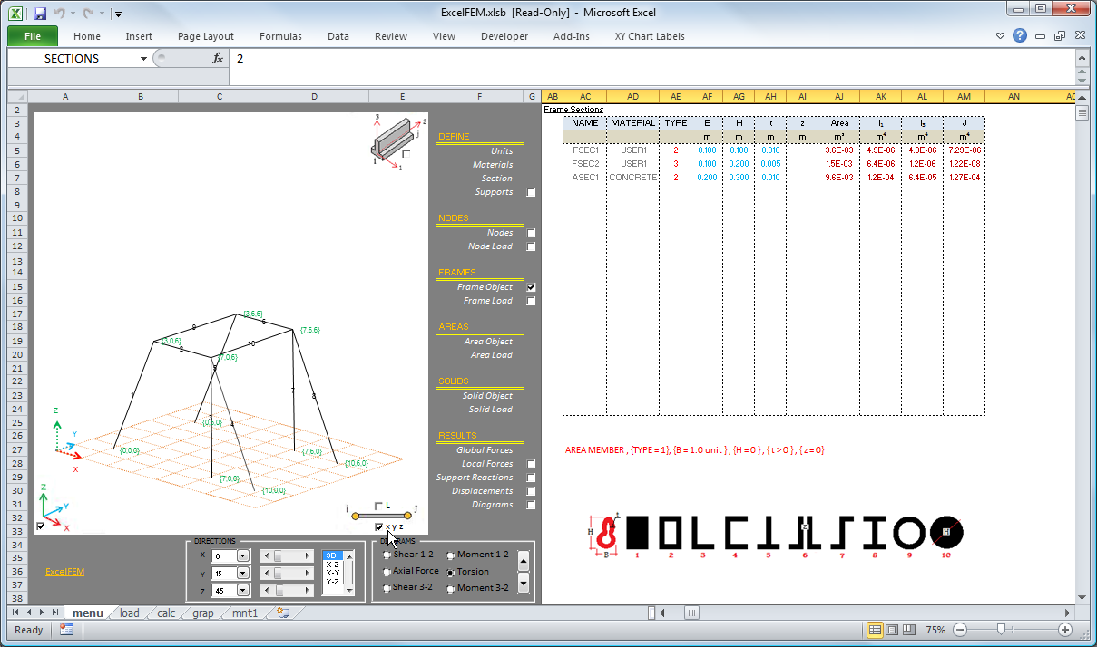
3) Define Member Sections
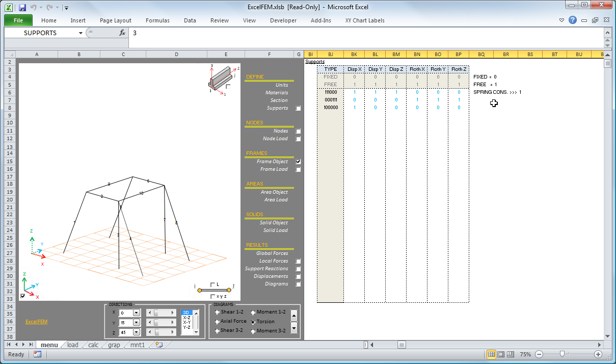
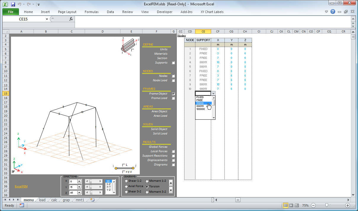
4) Define Node Supports
5) Define Node Positions
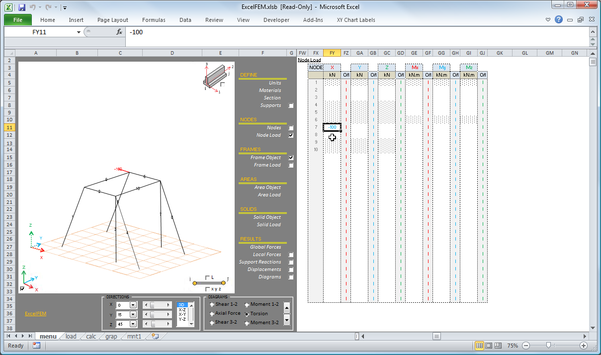
6) Define Nodal Loads
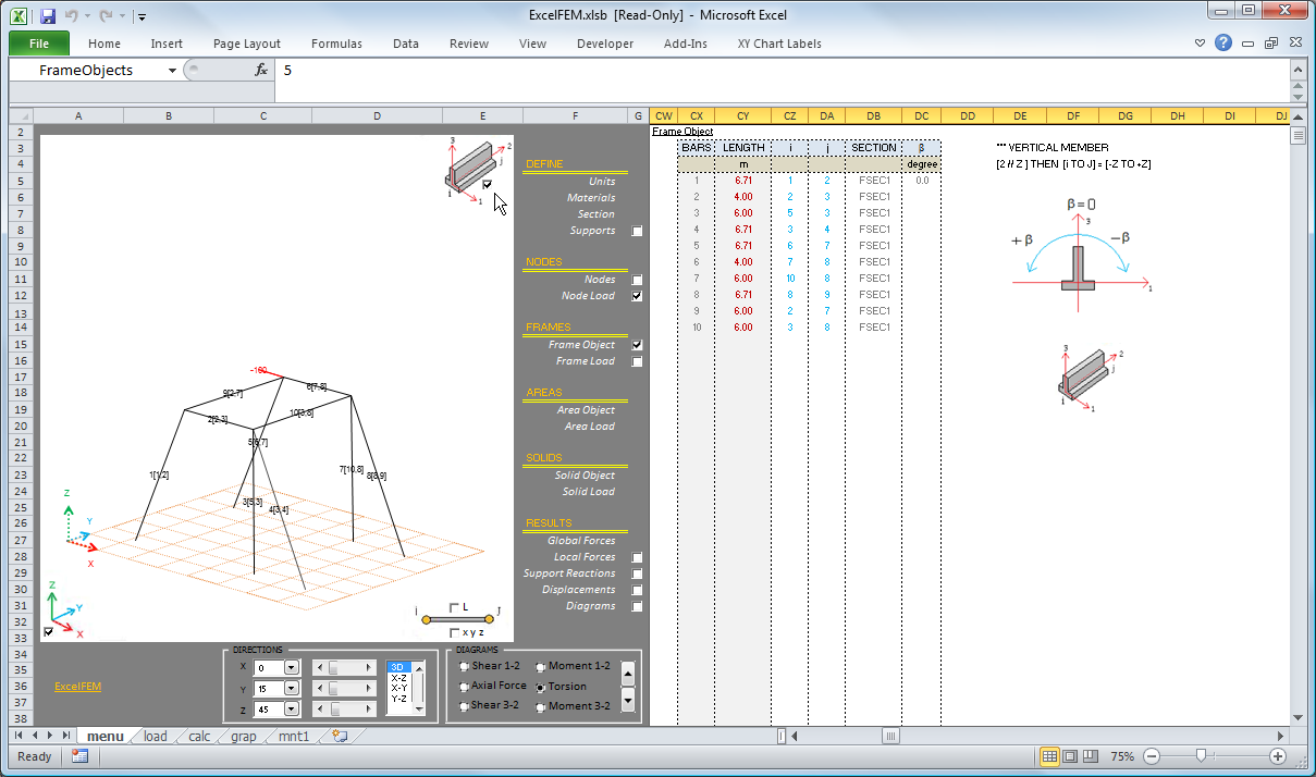
7) Define Members
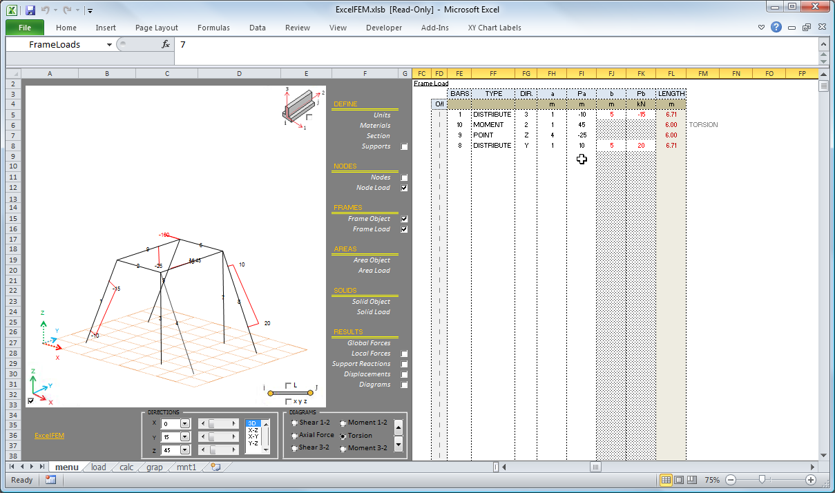
8) Define Member Loads
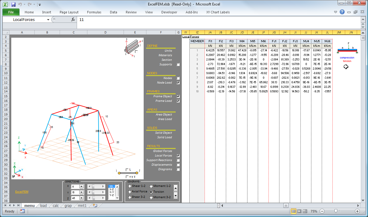
9) Examine Member Forces
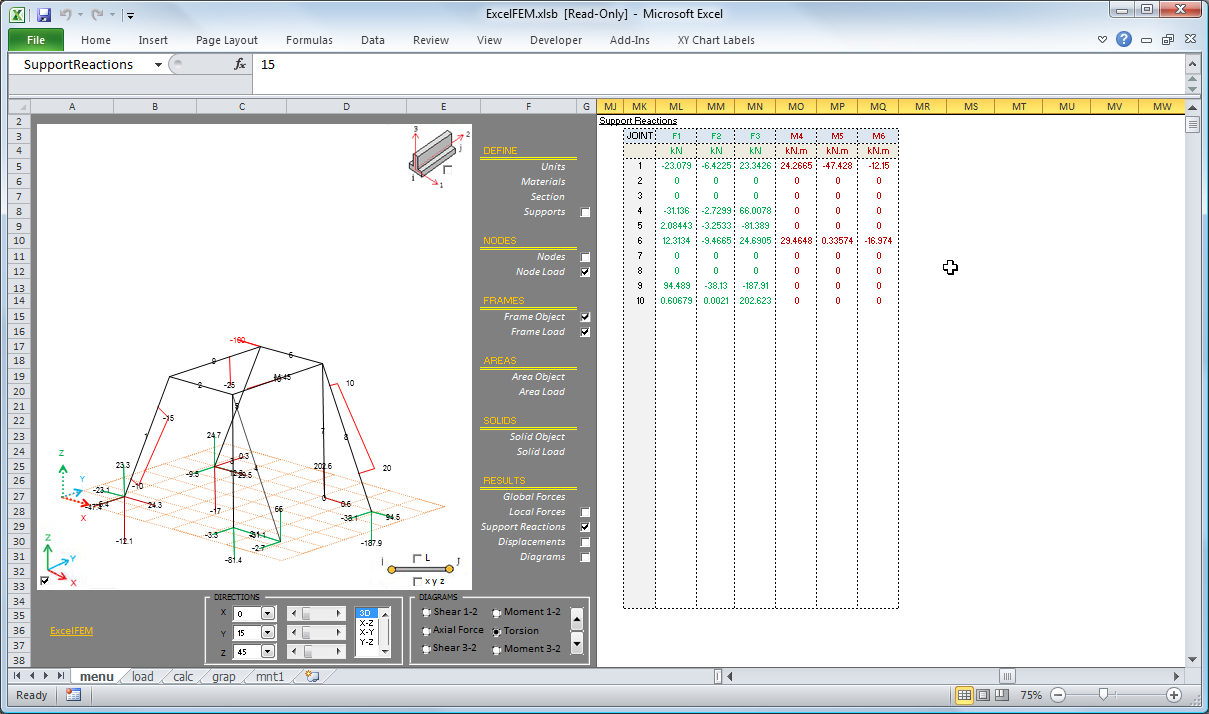
10) Examine Support Reactions
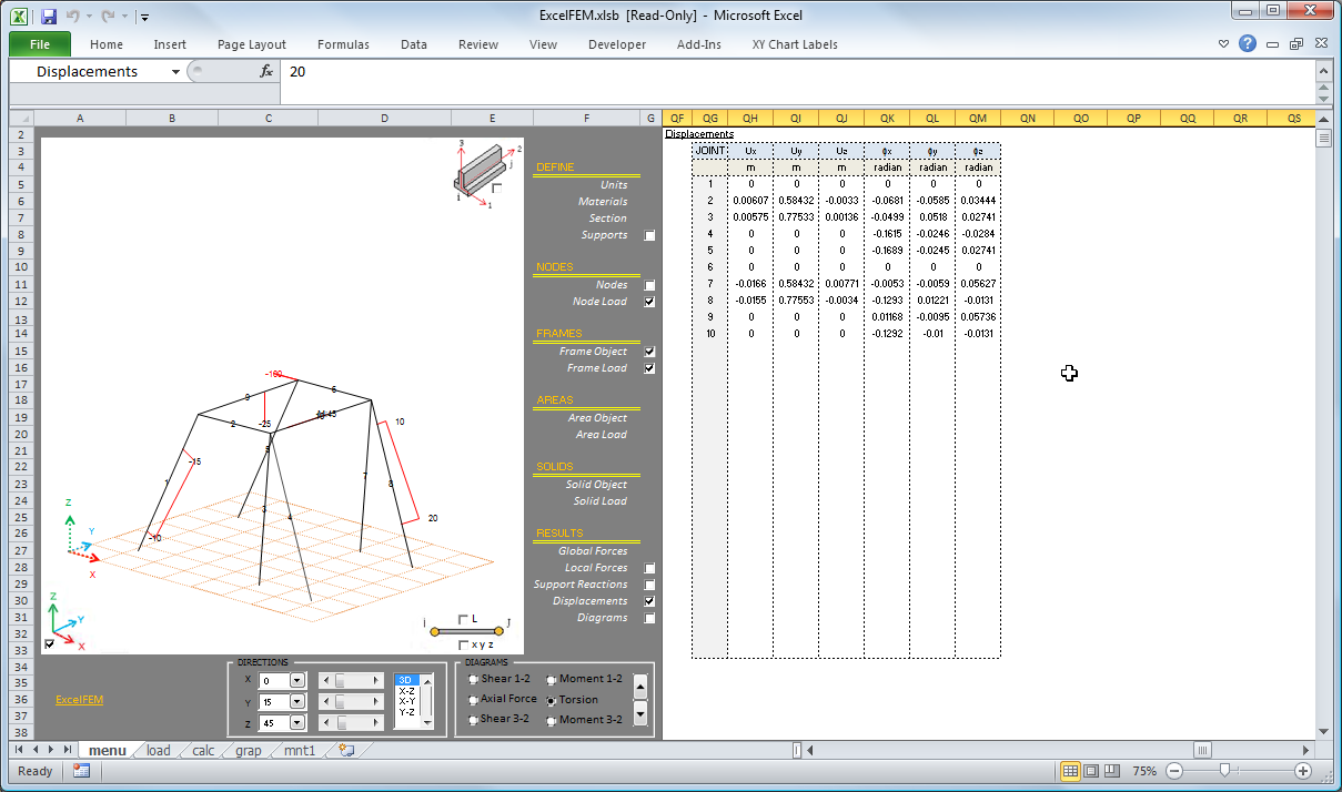
11) Examine Displacements
12) Plot Member Loads
 |
|
NO MACROS
PROPERTIES
Materials
Sections
Supports
NODAL POINTS & LOADS
Nodal Points
Nodal Loads
MEMBERS & LOADS
Members
Point Load
Moment Load
Distributed Load
CALCULATION RESULTS
Member Forces
Support Reactions
Displacements
DIAGRAMS
Axial
Shear
Moment
Deflections
FLOWCHART
VERIFIED AGAINST ANSYS
in this version;
loading control(load combinations)
moment,
-shear,
-axial,
-torsion
diagrams added.
interface has been changed.
was passed to xlsb.
note: no longer maintained, xls version.
Calculation Reference
Finite Element Analysis
Frame Analysis
Calculation Preview
Full download access to any calculation is available to users with a paid or awarded subscription (XLC Pro).
Subscriptions are free to contributors to the site, alternatively they can be purchased.
Click here for information on subscriptions.
Cheers!
As the last effort, can I get you to do the same comparison with the IPE 100 section. (Or did we already decide, there must be some special way you have to input the section into the ExcelFEM3d before the results are consistent with Staad/ Ansys?)
Thank you very much again John. You have been alot of help to me with this thread.
Section is solid square 5inch by 5 inch
E = 2.90E+07, Poisson Ratio = 0.3
Portal frame constructed from 3 members
Bottom members fixed
500lbs applied in horizontal direction in upper corner:
I obtained a good correlation between FEM3D and ANSYS results. I believe that you did not define the square section and assign it to the members correctly. Please see a summary of my findings below:
I hope this helps.
I just went to look at the .doc files that were posted on this thread. I agree the .doc file does say "0" for density on the staad.pro output report.
However, I just went and reviewed my model and the model has been assigned as steel and has the correct density.
Apparently, staad.pro has a bug in the report creation.
As such, I have attached another report for the IPE model.
This report is not as "pretty" in formatting (it is also generated by staad with no modifications made) but it does show that I have the correct "density" in my model.
Thank you both for not forgetting about me.
I think the subject spreadsheet is an amazing use of excel and I would love to be able to verify it so that I can continue with its use. Filename [NotAsPrettyReport_But_Correct___IPE_Sections.pdf](/images/fbfiles/files/NotAsPrettyReport_But_Correct___IPE_Sections.pdf), size 23414
The frame in this attachment is the reason the thread was started.
This FEM3D.xlsb when compared to the Staad.Pro analysis is a great deal different with respect to the reaction forces (force and moment).
The Staad.Pro Results (for the Portal Frame made of IPE 100s) can be found on the second page of this thread. (For comparison)
Would you happen to know what Mr. Babacan is trying to explain to me?
All looks well when I go into all of .xlsb files posted within this thread. (There are 3 total). 1.) IPE 100 Portal Frame Model in 3D.xlsb, 2.)Square Section Portal Frame Model in 3D.xlsb, 3.) Square Section Portal Frame Model in 2D.xlsb. The density looks fine in each of them because I have selected a "library" material in each of the 3 files.
In both the 3D version and 2D version I have selected "Steel" for the section called "RECT" which has been assigned to all beams in the Portal frames that are using a square section.
In the first 3D model posted in this thread, I used a "library" section that you created within your program. The "IPE 100" library section is automatically assigned with a material of "STEEL" which has a prescribed density within your FEM programs.
Please explain, or show me with a screenshot attached to your reply in this forum.
Thank you Turan!!!!! :-)
I agree, I think you "are on to something". It has to be an error in the usage (input) of the spreadsheet when using sections where there cross section differs in each respective axis. The note you spoke of has to be telling me something, I just don't quite understand it...
Turan is a very very smart man,and I doubt he is the one with the error. :-)
Hope we find a solution, this is an awesome use of excel, especially if we can get it work sufficiently.
Attached you will find the square section Excel FEM3D.
In the next post you will find the staad report with the same cross section properties applied to the beam elements.
I will try the suggestion with square steel elements. I cant remember but i believe i have already tried to rotate the IPE 100s in Turan's spreadsheet to see if my results would match the staad analysis (I believe that also didn't work). I'm not 100% sure on that though so i will run 2 examples. One with square shapes within staad and within Turan's spreadsheet. The second will be the rotation of the IPE 100s within Turan's spreadsheet to check against my initial staad run results. I will attach my results in the following post. Thank you again!!!
Then play with dimensions B and H to make an obvious difference in major and minor bending axis and this should help you understand what is happening.
One part in the instructions jumped out at me which read
I'll also try to get in touch with Turan and see if there is an easier way to check beam orientations.
Bear with us.
Thanks for sharing.
21-07-2011 "red/blue error" corrected.(thanks Santos Vega)
17-07-2011 "support reactions error" corrected.