BOXFRAME - CONCRETE BOX FRAME ANALYSIS
Description
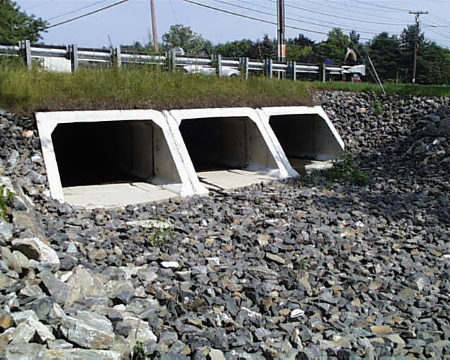
"BOXFRAME" is a spreadsheet program written in MS-Excel for the purpose of analyzing buried, externally loaded concrete box frame (tunnel) structures on compressible soil. Specifically, internal member forces for the top slab, walls, and bottom slab are determined. The internal member forces include the ultimate (factored) moments, shears, and axial compression. The internal moments are determined at each of the four corners, as well as the midspan points of the slabs and walls.
This program is a workbook consisting of five (5) worksheets, described as follows:
Worksheet NameDescription
DocThis documentation sheet
Box Frame (top & bot. equal)Box frame analysis for structures with equal top & bottom slabs
Box Frame (top & bot. unequal)Box frame analysis for structures with equal/unequal top & bottom slabs
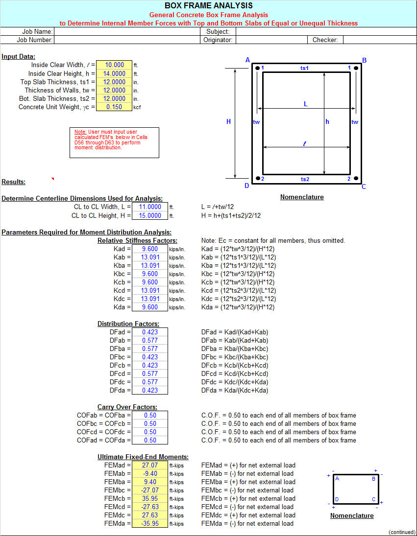
Box Frame (general)Box frame analysis for structures (requires user input of FEM's)
References & VerificationReferences and Verification Problem
Program Assumptions and Limitations:
- This program is based on the following references:
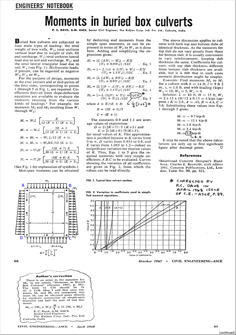
a. "Moments in Buried Box Culverts" - by P.C. Dave (page 66 from Civil Engineering Magazine, Oct. 1967)
b. "Author's Correction" (errata) - by P.C. Dave (page 89 from Civil Engineering Magazine, April 1968)
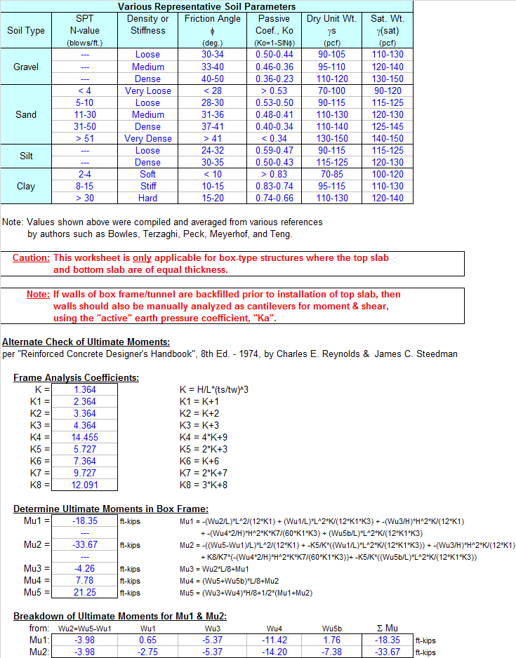
c. "Reinforced Concrete Designer's Handbook" (8th Edition, 1974 - Cement and Concrete Association) by Charles E. Reynolds and James C. Steedman
d. "Handbook of Structural Engineering" (2nd Edition, 2005 - CRC Press, Taylor & Francis Group) edited by W.F. Chen and E.M. Lui Section 2.4.3 - "Moment Distribution Method" (page 2-27 )
e. "Structural Steel Designer's Handbook" (3rd Edition, 1999 - McGraw-Hill, Inc.) by Roger L. Brockenbrough and Fredrick S. Merritt Section 3.38 - "Moment Distribution Method" by Ronald D. Ziemian, Ph.D.
-
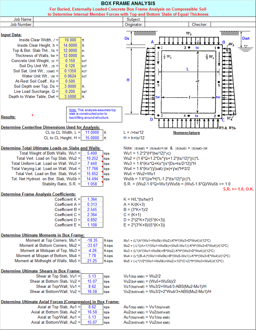
The "Box Frame (top & bot. equal)" worksheet provides a concise analysis and is based on References 1(a) and 1(b) from above, and is only applicable for box-type structures where the top slab and bottom slab are of equal thickness. The subsequent calculated moments at the 4 corners are checked against calculations performed using Reference 1(c) from above, as well as by the moment distribution method of analysis per References 1(d) and (1e) from above. These alternate checks are performed off of the main calculation page, and are done as a verification of the results of the original calculations.
-
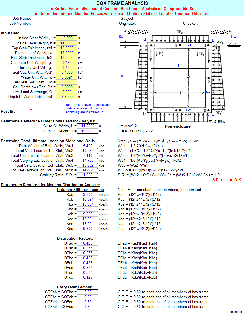
The "Box Frame (top & bot. unequal)" worksheet utilizes much of the same nomenclature, variables, and parameters as the previous mentioned worksheet. However, this worksheet allows for the box-type structure to have either equal or unequal thicknesses for the top and bottom slabs. Thus, this worksheet uses the moment distribution method of analysis to determine the moments at the corners per References 1(d) and (1e) from above.
-
For simplicity, both the "Box Frame (top & bot. equal)" and "Box Frame (top & bot. unequal)" worksheets only permit the selection of the depth (from ground surface) to the water table at 3 specific locations as follows:
a. Dwt = 0 (results in most conservative design)
b. Dwt = Ds + ts/2 or Ds + ts1/2
c. Dwt = Ds + ts + h + ts or Ds + ts1 + h + ts2
where:Ds = depth of soil cover over top slab
ts = thickness of both top and bottom slabs
ts1, ts2 = thickness of top and bottom slabs, respectively
Dwt = depth from ground surface to water table level
-
In both the "Box Frame (top & bot. equal)" and "Box Frame (top & bot. unequal)" worksheets, the centerlines of the slabs and the walls are used to define the horizontal length (L) and the vertical height (H) dimensions that are used for the purpose of the analysis.
-
In both the "Box Frame (top & bot. equal)" and "Box Frame (top & bot. unequal)" worksheets, the various loadings that are potentially considered include as follows:
a. Uniform live load surcharge pressure applied at ground surface.
b. Weight of dry soil above top slab, if water table level is assumed at top of structure or below.
c. Weight of saturated soil (buoyant soil weight + water weight) above top slab, if water table level is assumed at ground surface.
d. Dead weight of concrete for top slab.
e. Dead weight of concrete for both walls.
f. Uniform lateral pressure on walls resulting from surcharge plus lateral pressure from any soil above top slab and hydrostatic pressure from a water table level above top slab.
g. Triangular (varying) lateral pressure on walls resulting from soil and hydrostatic pressure from a water table level above base.
h. Soil bearing pressure against bottom slab from applied vertical loads, excluding dead weight of concrete for bottom slab which is cancelled out by reaction provided by soil.
i. Hydrostatic uplift pressure against bottom slab from any water table level above base minus dead weight of concrete for bottom slab.
-
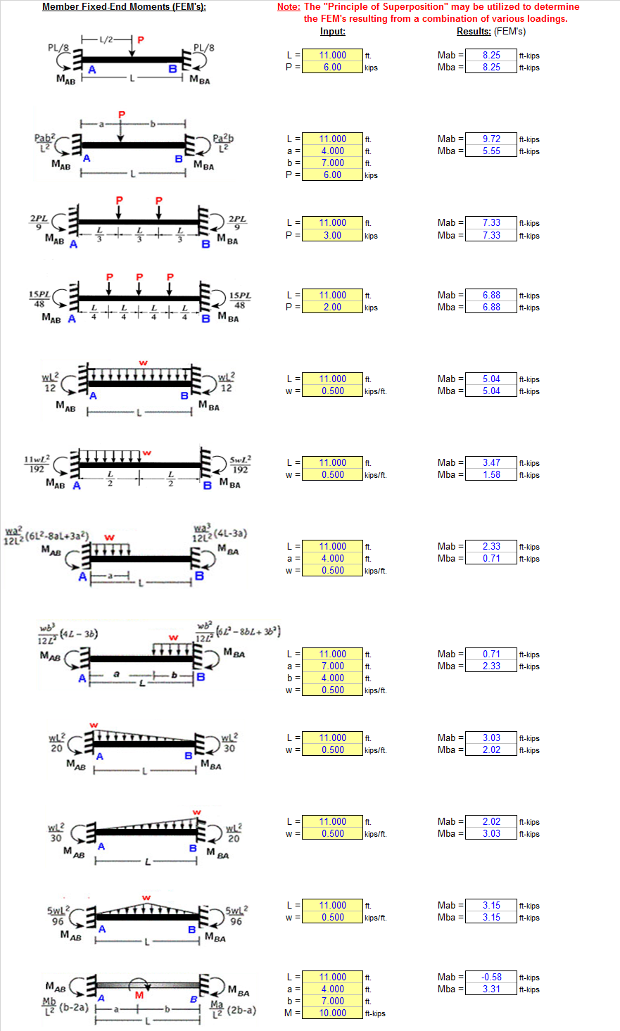
In the "Box Frame (general)" worksheet, the user is required to develop and input the ultimate fixed-end moments (FEM's) based upon the imposed loadings on the box frame. Thus, this worksheet allows for the analysis of a box frame subjected to virtually any type and/or combination of loadings. To the right and off of the main calculation page, there is user input to aid in determining member fixed-end moments for a variety of loadings. The "Principle of Superposition" may be utilized to determine resultant FEM's at each end. Also, the "Single-Span Beam" worksheet of the "BEAMANAL.xls" workbook may be utilized to facilitate the determination of the fixed-end moments (FEM's) for the top slab, bottom slab, and walls.
-
In all 3 calculation worksheets, the analysis and all of the results are based on an assumed 1'-0" (12") wide strip of slabs and walls.
-
In both the "Box Frame (top & bot. equal)" and "Box Frame (top & bot. unequal)" worksheets, the analysis used assumes that the top slab of the box frame/tunnel is constructed prior to backfilling around the structure. If the walls are to be backfilled prior to the installation of the top slab, then the walls should also be manually analyzed by the user as free-top cantilevers for moment and shear. Note that for a free-top cantilever wall condition, the user should use the active earth pressure coefficient,"Ka", instead of the at-rest earth pressure coefficient, "Ko", that is used for walls supported at the top in this program.
-
After the internal member forces have been determined by either of the 3 calculation worksheets in this workbook, if the user desires to perform a more detailed investigation of the moment or shear at a particular location in the slabs or the walls, the "Single-Span Beam" worksheet of the "BEAMANAL.xls" workbook may be utilized. In doing this, the user should select the "Simple" beam option, apply the calculated loadings along the length of the member, and finally apply the end moments as determined from the analysis. The user should compare the results of the "Single-Span Beam" worksheet for the end reactions (shears) and midspan moment to the values from the original analysis to make sure that the loads and end moments were applied and input correctly into the "Single-Span Beam" worksheet.
-
After the internal member forces have been determined by either of the 3 calculation worksheets in this workbook or from the "Single-Span Beam" worksheet, the desired version of the "RECTBEAM" workbook can be utilized to complete the flexural reinforcing and shear analysis.
-
The "References & Verification" worksheet shows the formulas used from references 1(a), 1(b), and 1(c) for verification of the programming logic using the example problem given input. The moment distribution method of analysis is performed to verify the results obtained from the reference formulas.
-
This program contains “comment boxes” which contain information including explanations of input items, etc. (Note: presence of a “comment box” is denoted by a “red triangle” in the upper right-hand corner of a cell. Merely move the mouse pointer to the desired cell to view the contents of that particular "comment box".)
Calculation Reference
Tunnel Structures
Box Frame Assessment
Culvert
Calculation Preview
Full download access to any calculation is available to users with a paid or awarded subscription (XLC Pro).
Subscriptions are free to contributors to the site, alternatively they can be purchased.
Click here for information on subscriptions.
Thanks
John
Excellence in Spreadsheets (Alex-cellance)
Thanks
If you are already doing so, you may want to try using "paste special", then select paste as "bitmap" when cutting and pasting graphics into spreadsheet. Causes slightly larger file size but crisper image.
Thanks again for your work.
John
Nice job, thank you.
Nick Barnitz