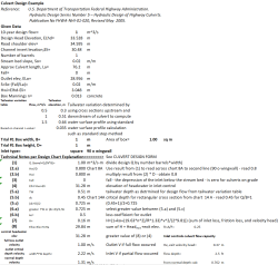
Culvert worksheet.xls

Description
Apply the fundamental engineering principle of culvert hydraulic design using standardized methods for determining flow capacity and control conditions.
Core Engineering Principle: Culvert Hydraulic Analysis
This calculation follows the FHWA Hydraulic Design Series principle that culverts can operate under different flow control conditions, and the designer must determine which condition governs to ensure adequate capacity and prevent flooding.
1. Flow Control Concept Culverts can be controlled by conditions at either end:
- Inlet Control: Flow capacity limited by the inlet's ability to accept water
- Outlet Control: Flow capacity limited by downstream conditions or barrel friction
- The calculation compares both conditions and uses whichever gives the higher headwater elevation (more restrictive)
2. Inlet Control Analysis
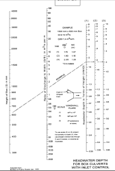
- Uses standardized design charts (Chart 8A) based on extensive testing
- Q/barrel per unit width (Q/B) = 1.00 m³/s-m is the key parameter
- For square wingwall inlet with this flow rate, chart gives Hwi/D = 0.8
- This means headwater depth = 0.8 × culvert height = 0.8 m
- Inlet control headwater elevation = 31.28 m
3. Outlet Control Analysis
- Considers tailwater conditions, friction losses, and critical depth
- Tailwater depth (0.51 m) from downstream channel analysis
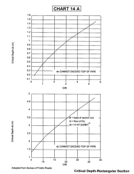
- Critical depth (0.45 m) from Chart 14A for rectangular flow
- Uses the greater of tailwater or (critical depth + culvert height)/2 = 0.725 m
4. Energy Loss Calculation The outlet control uses energy equation accounting for:
- Inlet loss (coefficient based on inlet geometry)
- Friction loss (Manning's equation with n = 0.013 for concrete)
- Velocity head (kinetic energy of flowing water)
- Exit loss (energy dissipated at outlet)
5. Hydraulic Radius Concept
- R = A/P = 0.25 (Area/Perimeter ratio)
- This geometric parameter affects friction losses
- Smaller hydraulic radius = more friction per unit flow
6. Manning's Equation Application
- Uses different roughness coefficients:
- Culvert barrel: n = 0.013 (smooth concrete)
- Natural channel: n = 0.035 (typical stream bed)
- Friction losses calculated using: f = (19.63 × n²)/R^1.33
7. Control Determination
- Inlet control headwater: 31.28 m
- Outlet control headwater: 29.84 m
- Inlet control governs (higher elevation = more restrictive)
- This means the culvert inlet cannot accept flow fast enough, creating backup upstream
8. Design Verification Process
- Design flow: 1 m³/s (10-year flood)
- Available head: 33.528 - 31.28 = 2.25 m (elevation difference between design head and computed headwater)
- Positive head available indicates culvert can handle the design flow
9. Velocity Analysis
- Full flow velocity: 1.00 m/s (if barrel flows completely full)
- Partial flow velocity: 2.22 m/s (higher velocity in smaller flow area)
- Normal depth velocity: 1.31 m/s (steady uniform flow condition)
This is like designing a funnel system - you need to check both whether the funnel opening can accept the flow rate and whether the tube can carry it away. The more restrictive condition determines the system's capacity. In this case, the inlet (funnel opening) is the limiting factor, so enlarging the culvert opening would be more effective than increasing the barrel size.
Calculation Preview
Full download access to any calculation is available to users with a paid or awarded subscription (XLC Pro).
Subscriptions are free to contributors to the site, alternatively they can be purchased.
Click here for information on subscriptions.


