Analysis & Design of Weld Groups
Description
Excel Template for the Analysis & Design of Weld Groups Subjected to Simultaneous Shear, Bending, Torsion & Axial Loading. Weld configuration can be any shape of multi-linear weld lengths in a plane. If present, unsymmetrical bending is taken into account in the analysis.
Dr Shaiq Khan is a Chartered Structural Engineer working freelance in the building trade. In his day to day work, he develops and uses computer software for the design and maintenance of buildings. This enables him to enhance the quality of work for his clients. It also shares and enhances technical expertise with fellow professionals in this country and abroad. More details at his website.
Calculation Reference
Weld Strength Analysis
The analysis and design of weld groups subjected to simultaneous shear, bending, torsion, and axial loading can be quite complex. Here is a step-by-step guide to approach the problem:
-
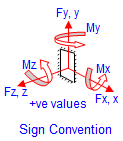
Determine the loading conditions: Identify the external loads (shear, bending, torsion, and axial) acting on the weld group. These loads can be obtained from the structural analysis of the entire structure.
-
Calculate the resultant force and moment: Combine the individual external loads to find the resultant force (R) and moment (M) acting on the weld group. The resultant force and moment will be used to calculate the equivalent stress on each weld.
-
Establish the weld group geometry: Determine the weld group's geometry, including the number of welds, weld length, weld size, and weld spacing. This information will be used to calculate the weld group's capacity.
-
Calculate the equivalent stress on each weld: For each weld in the group, calculate the equivalent stress caused by the combined external loads. This can be done using the following equation:
σ_eq = sqrt(σ_axial^2 + 3*(τ_shear^2))
where σ_eq is the equivalent stress, σ_axial is the axial stress, and τ_shear is the shear stress on the weld. Note that this equation assumes linear elastic behavior and is based on the von Mises yield criterion.
-
Check the weld capacity: Compare the equivalent stress (σ_eq) on each weld with the allowable stress for the weld material. The weld group is considered safe if the equivalent stress is less than or equal to the allowable stress for all welds.
-
Iterate the design, if necessary: If the weld group does not meet the capacity requirements, adjust the weld size, weld length, or weld spacing to increase the capacity. Repeat steps 4 and 5 to check the new design.
-
Verify weld group geometry: Ensure that the weld group's geometry meets the applicable code requirements for minimum spacing, edge distances, and weld length-to-width ratios.
-
Detailing and fabrication: Once the weld group design is finalized, provide the necessary detailing and fabrication information, including weld type, weld size, weld length, weld spacing, and weld material.
Always consult the relevant design codes and standards for specific requirements, limitations, and procedures when designing weld groups subjected to simultaneous shear, bending, torsion, and axial loading.
Calculation Preview
Full download access to any calculation is available to users with a paid or awarded subscription (XLC Pro).
Subscriptions are free to contributors to the site, alternatively they can be purchased.
Click here for information on subscriptions.