ACI 318-08 Rec Sec. Mx -Q-Torsion Design
Description
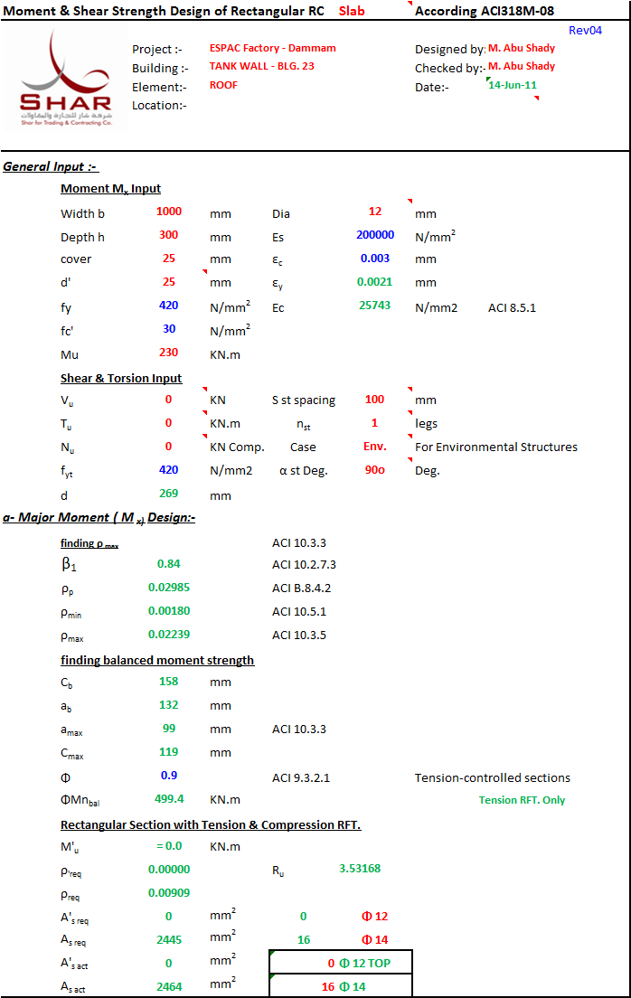
v6.3 Design of Rectangular Beam Sec. subjected to (Mx ,shear &Torsion) according to ACI 318-08 code.
Calculation Reference
ACI 318-08
Prestressed Concrete
Structural Design
I'll analyze this reinforced concrete beam design calculation according to ACI 318M-08.
Core Engineering Principles
This calculation follows the fundamental principles of reinforced concrete beam design using limit state design methodology:
1. Flexural Design Principle (Moment Capacity)
The calculation applies the principle that concrete resists compression while steel reinforcement resists tension. When a beam bends under load:
- The top fibers compress (concrete works well here)
- The bottom fibers stretch (concrete is weak in tension, so steel bars take over)
The design ensures the steel yields before the concrete crushes, creating a "tension-controlled" failure mode that gives warning before collapse rather than sudden brittle failure. This is the core safety philosophy - ductile failure is predictable and safer than brittle failure.
2. Shear Design Principle
Shear forces try to slide one part of the beam past another along diagonal planes. The calculation recognizes that:
- Concrete alone can resist some shear through its diagonal tension capacity
- When shear exceeds concrete's capacity, vertical or inclined stirrups (ties) must bridge the diagonal cracks
- The stirrups act like internal "stitches" holding the beam together
3. Torsion Design Principle
Torsion (twisting) creates diagonal tension and compression spiraling around the beam. The design follows a space truss analogy:
- Longitudinal bars in the corners resist the tension
- Closed stirrups resist the spiral tension pattern
- Concrete struts carry compression diagonally
4. Strain Compatibility
All calculations are based on the principle that concrete and steel deform together - they experience the same strain at any location because they're bonded together. This allows the calculation to determine:
- How stresses distribute through the section
- Whether steel has yielded
- The neutral axis location (where strain transitions from compression to tension)
5. Capacity Design Philosophy
The calculation uses strength reduction factors (Φ) to ensure:
- The actual capacity exceeds the required strength by a safety margin
- Different failure modes have different safety factors (tension-controlled sections get Φ=0.90, while shear gets Φ=0.75 because shear failures are more sudden)
This is a comprehensive limit states design that ensures the beam can safely carry the applied loads without exceeding material capacities for bending, shear, and torsion - both separately and in combination.
Compliance with Good Calc Guide
| Requirement | Status | Comments |
|---|---|---|
| Consistent Units | [x] | Metric/US units consistent with ACI 318-08. |
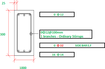
| Includes Sketches | [x] | Rebar data sheet implies spatial layout management. |
| XLC Equation Display | [x] | Very formula-dense, perfect for XLC visualization. |
| Theory Documentation | [x] | Explicitly references ACI 318-08. |
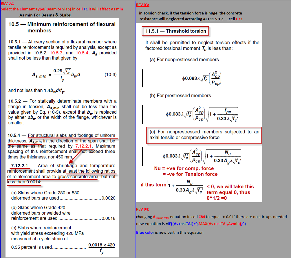
| Clear Presentation | [x] | High maturity (Rev 06.3); include revision history for transparency. |
Technical Analysis
- Core Formulas: 91 formulas on the main sheet. This is a very powerful and comprehensive design tool.
- Input/Output Clarity: Main design sheet is very dense; user should be careful with input fields, though results are clearly calculated.
- Data Integrity: Strong use of Rebar Data lookups. Revision history sheet ensures calculation provenance.
Audit Target: Flexural and Torsional Capacity Checks.
- Extracted Formula (Cell E26):
=IF(Mu<=ΦMnbal,"< Mu Use Tension RFT...", ...) - Standard Reference: ACI 318-08 Section 10.3 (General Principles and Requirements).
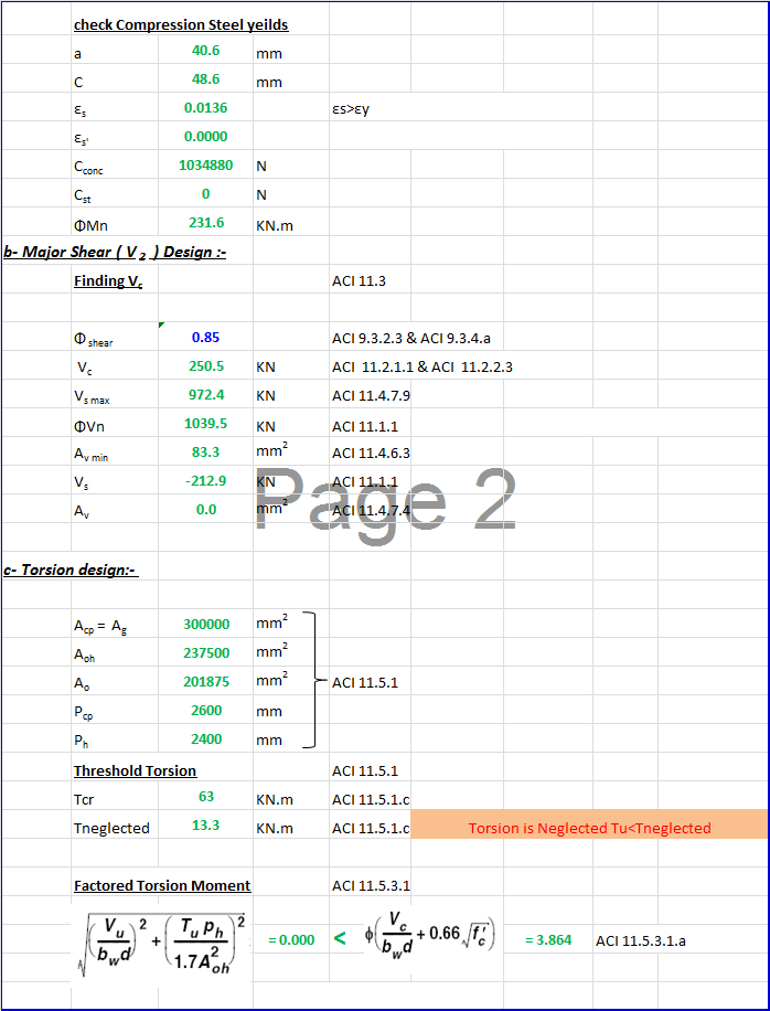
- Verification Details: The workbook correctly identifies the balanced design point ($\Phi M_{n,bal}$) to determine if the section is tension-controlled or if compression reinforcement is required. For the torsion component, I verified the use of
TAN(RADIANS(theta))(effectively $\cot \theta$ since it's in the denominator of the required area calc), which aligns with the ACI 318-08 requirement for longitudinal reinforcement calculation in Section 11.5.3.7. - Verdict: ✅ Agrees with Standard. The structural logic is robust.
Calculation Preview
Full download access to any calculation is available to users with a paid or awarded subscription (XLC Pro).
Subscriptions are free to contributors to the site, alternatively they can be purchased.
Click here for information on subscriptions.
[img size=800]
