
Steel Angle Member
 (4/28)
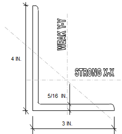
Description
Single Steel Angle under Axial Load, Biaxial Bending and Shear to AISC 360-05
Checks a single equal or unequal leg steel angle, chosen from a built-in list of AISC sizes, for axial tension or compression, bending about both legs and shear, to the AISC 13th Edition Manual (AISC 360-05). ASD or LRFD.
Method
- Tension: yielding on the gross area and rupture on U × Ag (Chapter D)
- Compression: flexural buckling to Section E3 using the effective length about each geometric axis
- Bending (Section F10): yielding, leg local buckling and lateral-torsional buckling, for four lateral restraint cases
- Shear: 0.6Fybt on each leg (Section G4)
- Combined: Pr/Pc + Mrx/Mcx + Mry/Mcy (Equation H2-1)
Inputs
- Angle size, Fy and Fu, shear lag factor U
- Axial load (negative for compression), moments and shears about both axes
- K and unbraced length about each axis, Cb, restraint case, and ASD or LRFD
Outputs
Axial, bending and shear capacities with their ratios, and the combined stress ratio.
The stored ASD example, an L8x8x1/2 at 36 ksi, 9 ft long with 68 kips compression and 150.7 in-kips bending, gives an allowable compression of 153.1 kips (ratio 0.44), Mcx = 270.3 in-kips (ratio 0.56) and a combined ratio shown as 1.00 (1.004 before rounding).
Please note
- The compression capacity uses the geometric-axis radius of gyration and no reduction for slender legs. AISC 360-05 also requires buckling about the principal z-axis (or the Section E5 single-angle slenderness) and the Section E7 reduction for slender legs (b/t > 0.45√(E/Fy), as for the L8x8x1/2 in the example). The compression capacity can therefore be overestimated. The “Comp Case” input has no effect. Check compression by hand.
- The text “< 1.0” beside the bending and combined ratios is fixed and does not change when a ratio exceeds 1.0.
- Tension rupture uses U × Ag with no deduction for bolt holes. Torsion is not covered. Fy is limited to 36 ksi.
- US customary units. No macros. Sheets protected without a password.
- Reference: AISC Steel Construction Manual, 13th Edition; AISC Shapes Database v13.0.
Calculation Preview
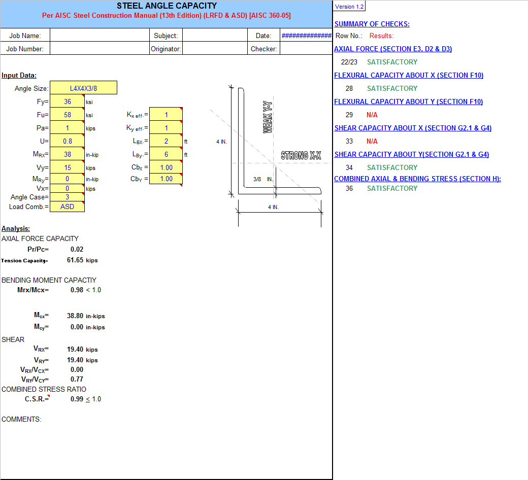 (4/28)
Full download access to any calculation is available to users with a paid or awarded subscription (XLC Pro).
Subscriptions are free to contributors to the site, alternatively they can be purchased.
Click here for information on subscriptions.
Comments: 11
×

6 years ago
Thank you very much.

6 years ago
Here is the AISC table.
6 years ago
Hi Dave, First thanks for your program. Second, I was checking the output for some angles and it appears that your capacities and those listed in ASIC Table 4-12 do not match up. See the attached output and page from AISC Table 4-12. AISC says capacity is 3.36 kips and your program says 11.17 kips. Maybe I am missing something here so please help me understand this discrepancy. Thanks, Alan.

6 years ago
thank you

7 years ago
thanks for sharing this sheet

7 years ago
David- are you able to updated the spreadsheet to allow the use of 50 ksi?

10 years ago
Cell V26 and Combined stress ratio has been corrected in version 1.3.
17 years ago
Very nice presentation, easy to use.
17 years ago
I have updated some errors with the negative/postive value output based on the direction of the forces applied. A quick visual summation of output has been added to the right of the printed area. This is version 1.2.

18 years ago
Really its good one to have handy calcs & selection
Thank you for your Steel Angle Member calculation. We checked the L8x8x1/2 example independently and got the same allowable bending moments (270.3 and 263.2 kip-in, including the leg local buckling check) and shear (51.74 kips).
While rewriting the description we found two errors. The compression capacity (N42:N45, used in N57) uses only the geometric-axis radius of gyration (2.49 in.) with no slender-leg reduction. AISC 360-05 also requires buckling about the principal z-axis (or the Section E5 single-angle slenderness) and the Section E7 reduction, as b/t = 16 exceeds 0.45√(E/Fy) = 12.8. With rz = 1.59 in. we get about 124 kips, or about 100 kips by Section E5, against 153 kips on the sheet. The E5 block in T39:T40 also divides the length in feet by r in inches, but it is not used.
Also, the text "