Frames
0 ContainersFiles in Frames
Order by
ElasticFrames-Roark.xlsx
Short Description:

Submitted By:
Last Modified
28 Feb 2011
Downloads:
200
Rating:

FRAME (metric).xls
Short Description:

Submitted By:
Last Modified
11 Oct 2016
Downloads:
363
Rating:
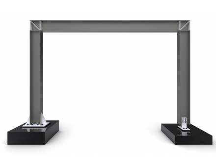

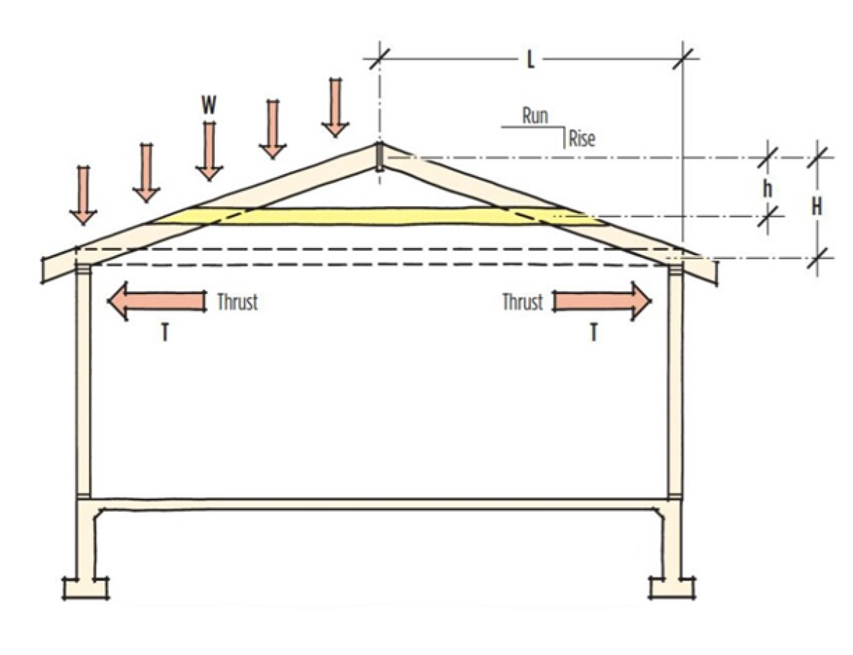
Kleinlogel
Short Description:
Various frames: rectangular, gable, and skillion, with pinned and fixed bases. Each is set up with...
Submitted By:
Last Modified
11 Apr 2010
Downloads:
297
Rating: