Pins and Joints
0 ContainersFiles in Pins and Joints
Order by
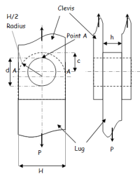
Aerospace_lug_analysis.xls
Short Description:
Submitted By:
Last Modified
03 Oct 2008
Downloads:
425
Rating:


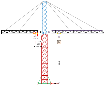
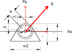
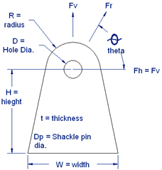
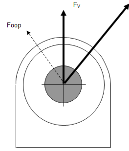
API PADEYE Design
Short Description:

Submitted By:
Last Modified
28 Apr 2008
Downloads:
1382
Rating:


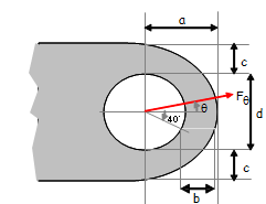
Clevis and lug design - Peterson's
Short Description:
Submitted By:
Last Modified
29 Mar 2011
Downloads:
1453
Rating:
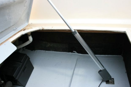
Hatch/Door Actuator Design
Short Description:

Submitted By:
Last Modified
11 Jul 2014
Downloads:
57
Rating:


Pin and Lug - Static and Fatigue.xls
Short Description:
Submitted By:
Last Modified
10 Aug 2023
Downloads:
417
Rating:

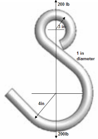
S-hook design.xls
Short Description:
Submitted By:
Last Modified
24 Jan 2007
Downloads:
256
Rating: