Plates
0 ContainersFiles in Plates
Order by

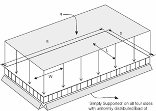
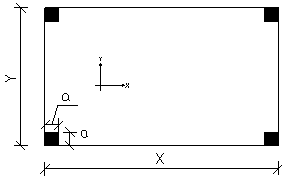
Bending of plates
Short Description:

Submitted By:
Last Modified
14 Apr 2010
Downloads:
569
Rating:


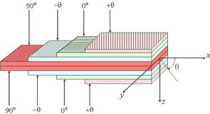
Composite Laminated Plate
Short Description:
Submitted By:
Last Modified
19 Jul 2014
Downloads:
94
Rating:

Composite Panel Calculations.xlsx
Short Description:
Submitted By:
Last Modified
19 Feb 2010
Downloads:
201
Rating:


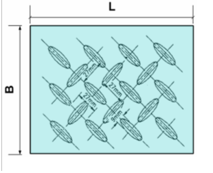
Floor plates and orthotropic decks
Short Description:
This spreadsheet is an update for Michael Henry's excellent 2008 sheet for Durbar plate. From a simple user defined support condition, it calculate...
Submitted By:
Last Modified
03 Dec 2024
Downloads:
27
Rating:


Honeycomb Beam & Panel Calculations
Short Description:
This spreadsheet has been developed to allow design engineers to quickly size honeycomb panels with a minimum of work. The ca...
Submitted By:
Last Modified
07 Jan 2016
Downloads:
258
Rating:

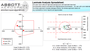
Laminate_Stress_Strain_Analysis.xls
Short Description:

Submitted By:
Last Modified
03 Oct 2008
Downloads:
262
Rating:

More Plate Bending
Short Description:
Submitted By:
Last Modified
25 May 2011
Downloads:
273
Rating:
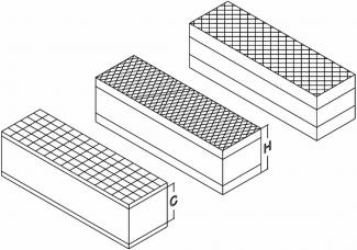
Plate Bending for Orthotropic Laminates
Short Description:

Submitted By:
Last Modified
07 Apr 2010
Downloads:
101
Rating:
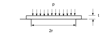

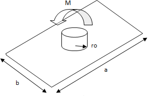
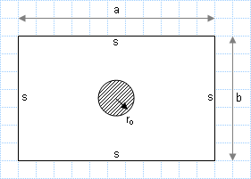
Rectangular plate loaded with circular load at centre.xls
Short Description:
Submitted By:
Last Modified
29 Oct 2007
Downloads:
671
Rating:

Thickness calculation for bottom plate of a Rectangular Tank subjected to hydrofill pressure
Short Description:
Submitted By:
Last Modified
19 Jun 2025
Downloads:
5
Rating: