Geotechnics
0 ContainersFiles in Geotechnics
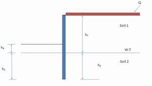
Bearing Capacity in multi-layer soils
Calculation of bearing pressures to BS EN 1997-1 (EC7) and UKNA (Design Approach 1) for soils with more than one la...
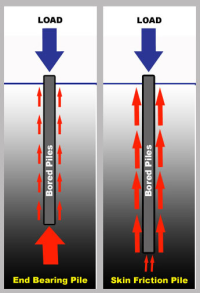
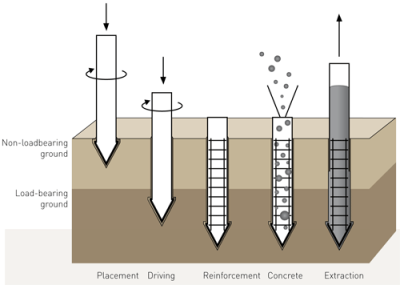
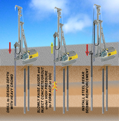
bore pile design bs 8004
Spreadsheet to calculate pile bearing capacity of drilled shaft foundation - bore pile according to BS 8004. For preliminary design pur...
Consolidation settlement due to embankment load and additional external load
This excel calculate consolidation settlement due to embankment load and additional external load e.g. railway constr...
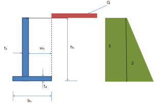
Drained Strip Foundation En1997
STRIP FOUNDATION (EN1997-1:2004) Purpose of calculation Design and alalysis of two leaf block basic strip foundation ...
FOOTINGS.xlsx
Civil engineers design footings to provide a stable and strong foundation for...

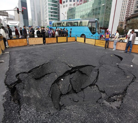
Liquefaction
Liquefaction Induced Calculation During Earthquakes
The purpose of this spreadsheet is to analyse liquefaction induced settlem...


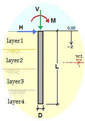
Single Pile Load vs settlement

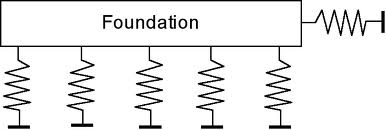
SOIL SPRING CONSTANTS FOR FOUNDATIONS


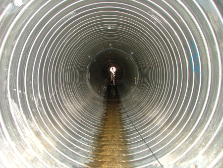
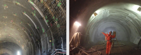
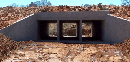
Tunnel Support Design
This excel sheet discusses the calculations of tunnel support like rock bolt design, shotcrete calculations, steel ribs design, etc. based on Indian codes.