Structural Details
0 ContainersFiles in Structural Details
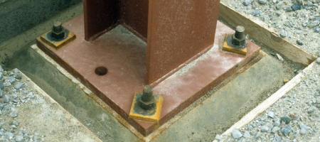
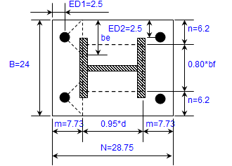
ACI 318-14M BASE PLATE DESIGN
COLUMN BASE PLATE DESIGN (ACI318-14M, PIP STE05121) LRFD PROCEDURE
AISC 14.1 Properties Viewer.xls


Analysis of Sheet Pile Wall - Cantilevered and Anchored


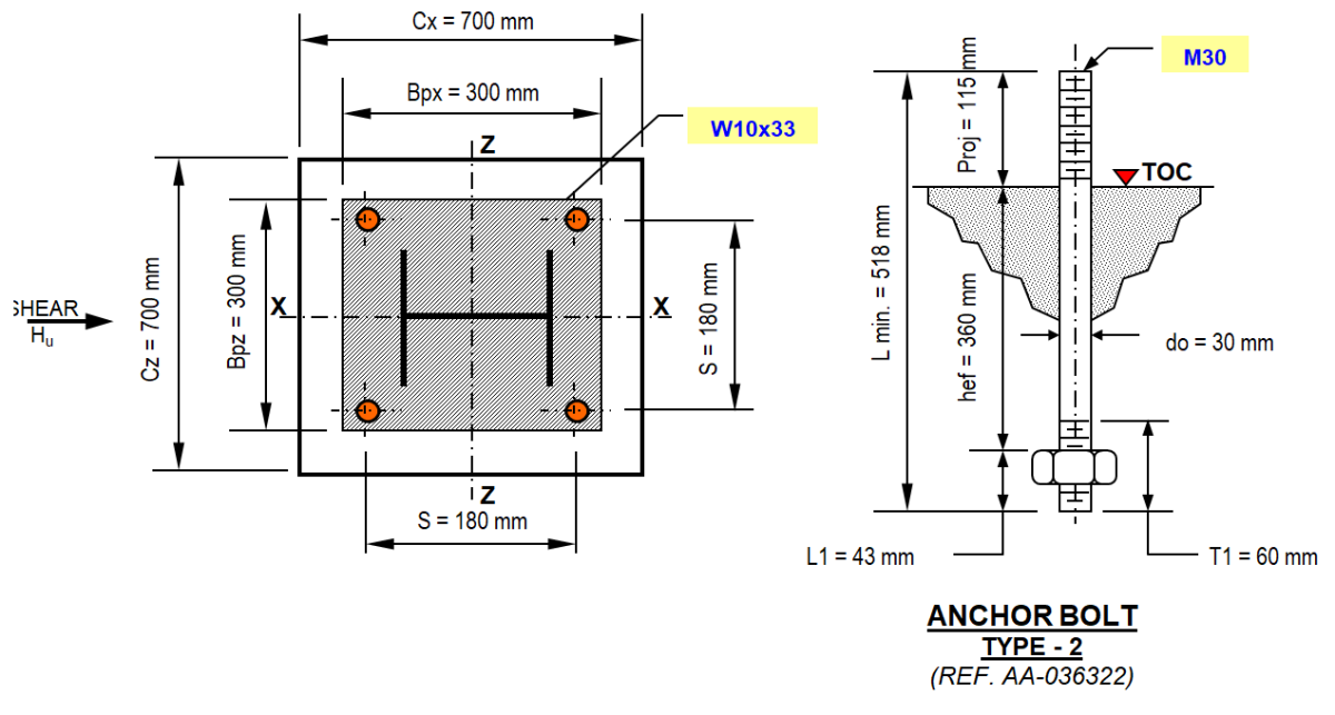
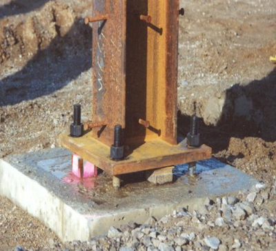
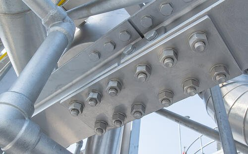
ANCHOR BOLT_BASE PLATE
Anchor bolt design is a crucial aspect of structural engineering, particularly in connecting structural elements to concrete foundations or other c...
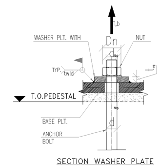
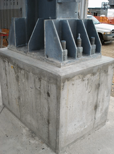
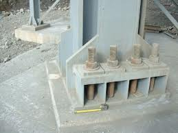
Anchor Chair Design
Anchor Chair Design as per ACI318M-14
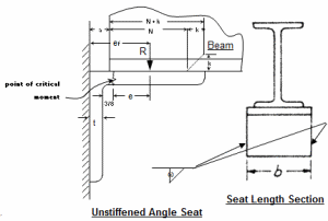
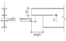
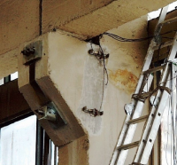
Angle Seat Detail

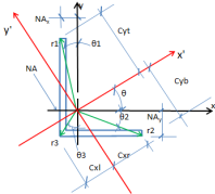

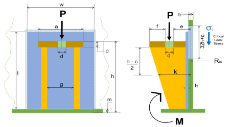
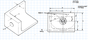
Angle type tension fitting.xls
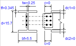
BASE PLATE & END PLATE
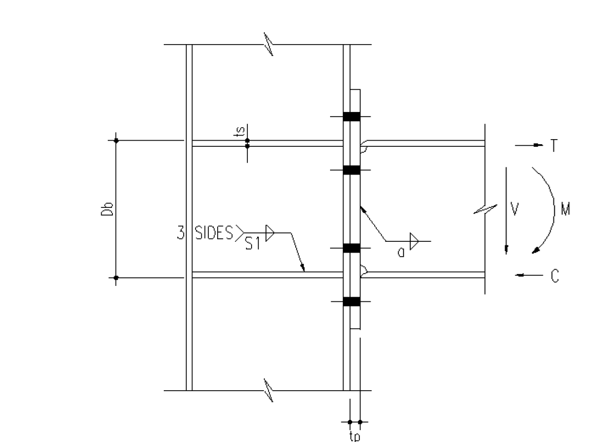
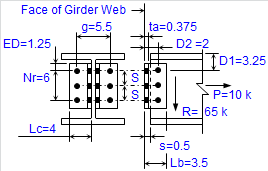
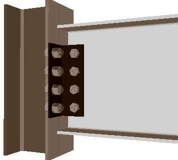
Structural steel moment connection using bolts and welds
TENSION ZONE
Connection Geometry:
Typically involves an end plate welded to the b...

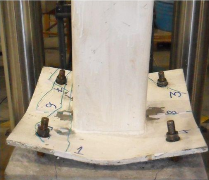
Base Plate analysis


Base plate design - fixed condition - Eurocode

BEAMCOL9.xls
"BEAMCOL9" is a spreadsheet program written in MS-Excel for the purpose of analysis and code checking of steel beams and columns. Specifically, bea...


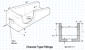
Channel type tension fitting.xls


ClipConnTable.xls
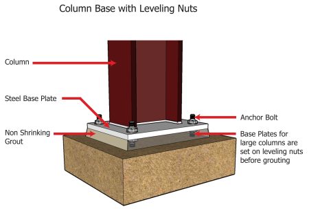
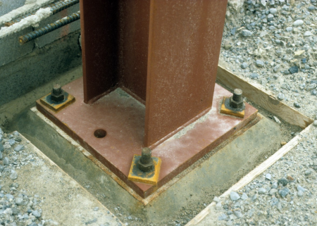
Column base design
Column base hinge Type
Column base design BS code
Column base design BS code


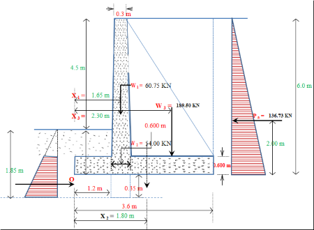
Counterfort Retaing Wall of 6 m Height Design & Cost
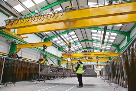
CRANE GIRDER DESIGN BS5950
Calculation Reference
Crane Design
BS5950
Structural Design
...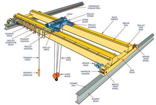
Crane runway design based on DIN standard
Parameters
Hoist type, Hoisting speed, VH, Operation, Type of girder, Safe working load, Support length, L, , Crane group , Gird...

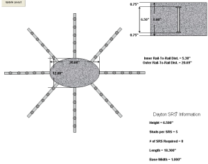
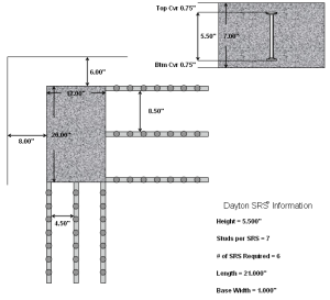
Dayton-Shear-Reinforcement-System-For-Round-Columns.xls


Dayton-Shear-Reinforcement-System-For-Square-Columns.xls