Wind & Snow
0 ContainersFiles in Wind & Snow
Order by


Actions from Wind to BS EN 1991-1-4 and UKNA
Short Description:
Calculation of peak wind pressure to BS EN 1991-1-4 and the UK National Annex, used with either force coefficients or pressure...
Submitted By:
Last Modified
31 May 2022
Downloads:
25
Rating:


ASCE 7-10 CODE ICE LOAD ANALYSIS PROGRAM
Short Description:

Submitted By:
Last Modified
31 Dec 2014
Downloads:
202
Rating:
ASCE 7-10 CODE SNOW LOAD ANALYSIS PROGRAM
Short Description:
'ASCE710S' --- ASCE 7-10 CODE SNOW LOAD ANALYSIS PROGRAM
Program Description:
'ASCE710S' is a spreadsheet program written i...
Submitted By:
Last Modified
08 Apr 2024
Downloads:
426
Rating:


ASCE 7-10 Load Combinations
Short Description:
Submitted By:
Last Modified
06 Mar 2014
Downloads:
409
Rating:


ASCE705W Wind Loading
Short Description:
Submitted By:
Last Modified
29 Apr 2013
Downloads:
3465
Rating:


More Retaining Wall Calculations
Short Description:
Let's break down the key components:
Input Parameters:
Soil Properties:
Friction angle (φ) = 30 degrees Cohesion (c) = 0 Soil unit we...
Submitted By:
Last Modified
23 Nov 2024
Downloads:
361
Rating:

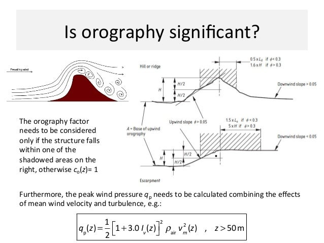
Orography Factor to BS EN 1991-1-4 and UKNA
Short Description:
Submitted By:
Last Modified
31 May 2022
Downloads:
9
Rating:

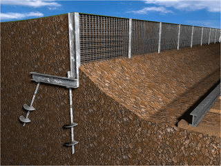
POLEFDN.xls
Short Description:
'POLEFDN' is a spreadsheet program written in MS-Excel for the purpose of analysis of a pole foundation assuming t...
Submitted By:
Last Modified
11 Oct 2016
Downloads:
2813
Rating:


schWindAssessment
Short Description:

Submitted By:
Last Modified
11 Apr 2010
Downloads:
236
Rating:


Single span portal culvert
Short Description:

Submitted By:
Last Modified
04 Aug 2012
Downloads:
261
Rating: